Knurling
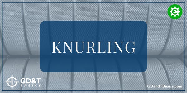
Knurling is a process used to create a pattern on the surface of a material by displacing or deforming the surface.
To understand the thread requirements on your drawing, you need to know common standard thread information. In this article, we will be discussing thread diameters, threads per inch and thread pitch.
Precision tops the list of priorities in CNC machining since being off by a few thousandths is enough to cause serious errors. While no machine yields a 100% accuracy rate, specific approaches have been undertaken to manufacture components efficiently and economically.
We at GD&T Basics are excited to be participating in this year’s 2022 International Manufacturing Technology Show (IMTS) held in Chicago, Illinois, September 12-17, 2022.
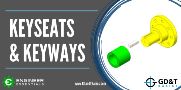
A keyed joint is used to ensure orientation or restrict rotational movement between parts, as in the case of joining a shaft with a coupling. We discuss how a keyed joint is made and inspected in this article.
In this article, we outline the basic process for adding GD&T to your drawing using SolidWorks. The accompanying video goes into full detail, walking through the entire process for an example drawing.
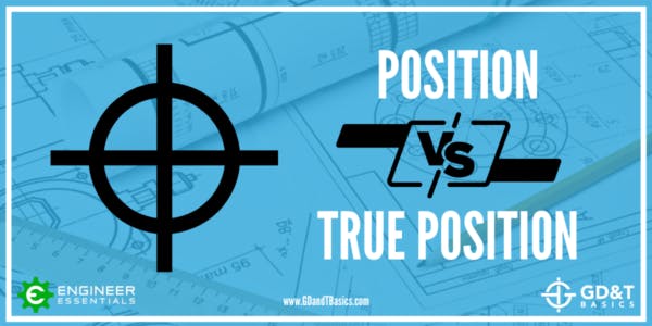
Though many people refer to the GD&T Position symbol as "True Position," they are not the same thing. Read on to learn the difference between Position and True Position and how they work together to define the position of a feature.
Tolerance stacks can be a nightmare. However, when using GD&T rather than coordinate dimensioning, tolerance stack-ups within a part can be avoided.
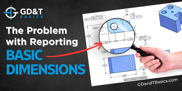
Confused about basic dimensions? Jason explains their purpose, why they aren't recorded on inspection reports, and what should be documented instead.
What is a Datum Reference Frame? Datums are used in Geometric Dimensioning and Tolerancing drawings to create a reference system for inspecting a manufactured part. This reference system is called a Datum Reference Frame (DRF)....
Having a good understanding of Geometric Dimensioning and Tolerancing is very important for anyone working in a mechanical field. GD&T is the language used in design, manufacturing, and quality inspection to communicate on engineering prints....
Making the decision to invest in GD&T training isn’t always easy. And even once you’ve made that call, you still need to pick a program that’ll teach your team what they need to know. While the concepts...
Today, I’m the President of Engineer Essentials, a company I founded to help engineers, machinists, inspectors, students and others learn the concepts of geometric dimensioning and tolerancing (GD&T). I’m a mechanical engineer and a Certified...
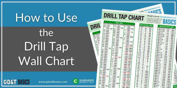
The most common way to produce an internal thread is to drill a hole and then use a tap to produce the thread. This is usually referred to as a tapping drill for the size...
GD&T Basics has partnered with Mitutoyo to demonstrate how to set up and inspect a part using a CMM. In this video, we examine a part designed as a training aid by Mitutoyo, inspecting it...
Geometric dimensioning and tolerancing (GD&T) is a system in manufacturing that can be traced back to the 1940s. It was developed by Stanley Parker while he worked at Royal Torpedo Factory in Alexandria, West Dunbartonshire,...
This 3-part series is great for designers or anyone who may be applying things to an engineering drawing. In this series, we’ll review the top 3 things that manufacturing and quality departments wish you knew...
To determine when to use Profile of a Surface or Coordinate Dimensioning, let’s first look at what the 2009 ASME Y14.5 Geometric Dimensioning and Tolerancing Standard tells us. Paragraph 2.1.1 was revised to emphasize/encourage the...
How are tolerance limits defined? The previous articles in our Intro to Tolerances series have answered the questions, “What is a tolerance?” and “Why use tolerances?” This third and final article in the series explores...
Why use tolerances? In our previous article, “What is a Tolerance?” we introduced the concept of manufacturing tolerances and why they are necessary. In this article, we are going to focus on the benefits of...
What is a tolerance? If you take a look at an engineering drawing, you will notice that there are always limits, or tolerances, placed on a dimension. Why does the designer do this? When a...
What is the difference between the ISO and ASME GD&T standards? Read on to find the answers to these questions and more – and see our GD&T Standards Comparison Chart available to download for free below....
The ASME 2018 Y14.5 GD&T Standard contains a few significant changes, including the elimination of the concentricity constraint. Check out this video article for more on this change!
Properly defining, qualifying, and referencing datum features is essential to ensure that parts are properly manufactured and inspected. To begin exploring proper use of datum features, it is helpful if we first review definitions and...
There can be a lot of confusion when dealing with circularity – especially when identifying the tolerance zone compared to how Rule #1 of Geometric Dimensioning and Tolerancing controls it. In this video, we provide...
This video is in response to a question that we received on our question line from Alex. His question is as follows: “Is there a best-practice way to use Position (instead of Symmetry) to control...
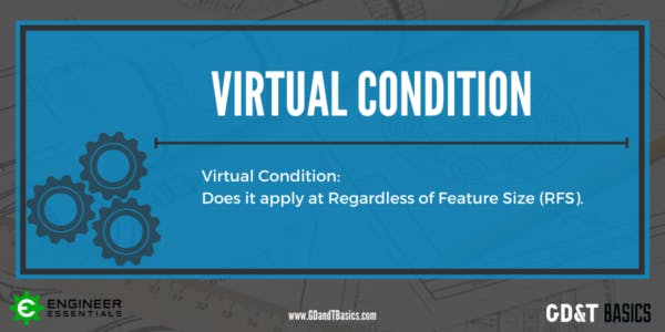
In this question line video, Brandon discusses Virtual Condition and whether it can apply at Regardless of Feature Size (RFS). What is Virtual Condition (VC)? When a feature is controlled with the Maximum Material Condition...
In this video, we respond to a question asking how using Geometric Dimensioning and Tolerancing can affect internal or vendor-provided manufacturing and inspection processes. It is important to remember that the goal of GD&T is...
What is the difference between unilateral and bilateral tolerance in a profile of a surface callout? In this post, Brandon explains the difference and gives examples of how they are used. Profile of...
This video is in response to a question that we received on our question line from Amar. Amar’s question is as follows: “If we are given a BASIC radius of 10mm, and on the radius,...
Orthographic views allow us to represent a 3D object in 2D on a drawing. Orthographic views can show us an object viewed from each direction. How the views are laid out on a drawing depends...
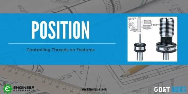
This video is in response to a question that we received on our question line from Tim. Tim’s question is as follows: “We tend to use true position on threaded holes. Is this valid? If...
This video is in response to a question that we received on our question line from Jamee. Jamee’s question is as follows: “For parallelism of a circular feature of size (axis) can you use two...
This video is in response to a question that we received on our question line from Lokesh. Lokesh asked us if a material modifier can be used with cylindricity. Geometric Dimensioning and Tolerancing modifiers are...
This video is in response to a question that we received on our question line from Amber. Amber asked us if the tolerance value for circularity can be obtained by subtracting the upper limit of...
This video is in response to a question that we received on our question line from Ignacio. Ignacio asked us if it is a bad practice to reference three datums in a single drawing callout...
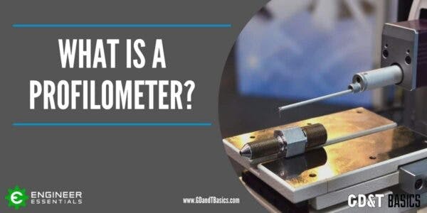
Ever wonder how surface finish is measured? For inspection, we use a device called a Profilometer. In this article, we will show you how profilometers work and highlight their advantages and limitations. What is a...
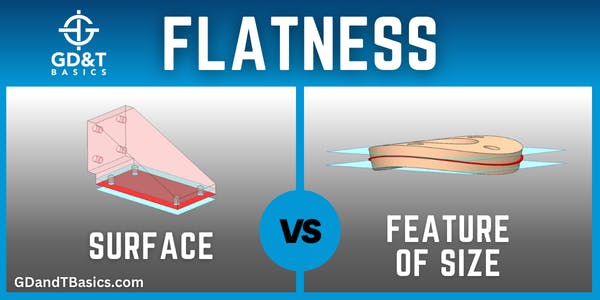
In this video, Brandon discusses the difference between measuring Flatness of a Surface and Flatness of a Feature of Size (FOS). Flatness of a Surface Surface flatness is the type of flatness that most people...
A question we are often asked here at GD&T Basics is, “what is a basic dimension?” – These dimensions are often fairly confusing as they look very similar to other dimensions you may be familiar...
In this video, Brandon discusses basic dimensions and why they should not be recorded on an inspection report. What Are Basic Dimensions? Basic dimensions are used in Geometric Dimensioning and Tolerancing to describe the theoretically...