
Many people refer to the GD&T Position symbol as “True Position.” However, this symbol is actually only referred to as “Position” in the ASME Y14.5 standard. Why make this distinction? Because “True Position” refers to the exact position of a feature as defined by basic dimensions, while the Position symbol is used to indicate the positional tolerance – the allowable amount of variation of that feature from its True Position.
The difference between True Position and position tolerance can be illustrated as throwing darts. When throwing darts at the bullseye, we are aiming for the exact center. This exact center represents True Position. However, when we throw darts, it’s likely that most will not hit the exact center of the bullseye. How far away from the exact center is acceptable? This is determined by the position tolerance.
Let’s look at the drawing example in Figure 1. The location of the hole in the center of the part is being controlled by Position. The basic dimensions of 2.5” from the bottom of the part (Datum Feature B) and 2.5” from the left side (Datum Feature C) locate the perfect location for the axis of the hole – the True Position of the hole. The tolerance on this location is indicated through the feature control frame for the hole. This feature control frame tells us that the hole has a diametrical position tolerance of 0.005”.

Figure 1: Part Drawing with GD&T Position Tolerance on Hole Location
When we think about this in terms of our dart board illustration, we would picture the drawing as seen in Figure 2. Notice that the True Position, the center of the bullseye, is located by the basic dimensions highlighted in red. The position tolerance is illustrated by the blue ring surrounding the True Position. To pass inspection, the measured axis of the hole must fall within that diametrical position tolerance zone.
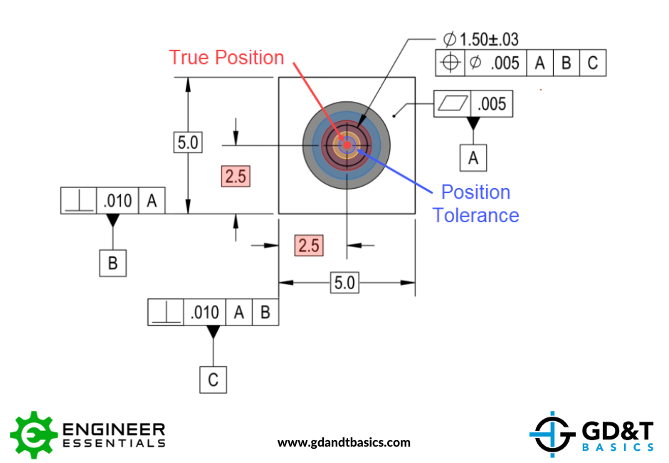
Figure 2: Illustration of Position as a Bullseye
One more thing to note is that we are not just looking at this axis as a 2-dimensional location. The measured axis of this hole must lie entirely within the cylinder created by this diametrical position tolerance as shown in the 3-dimensional model shown in Figure 3.
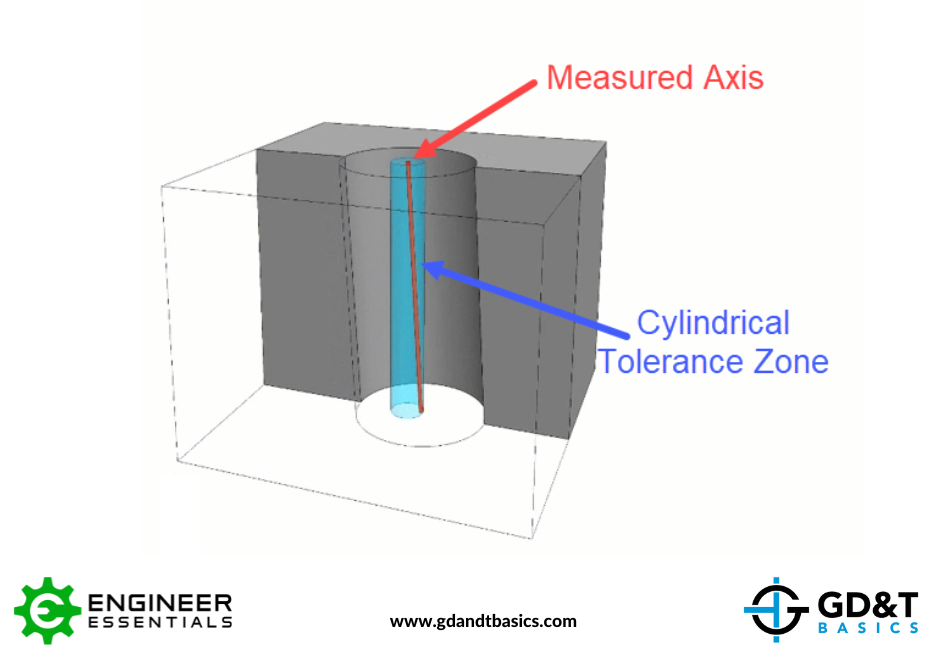
Figure 3: Position Tolerance as a Cylindrical Tolerance Zone
In summary, True Position is the exact location that we are aiming for, and the Position control tells us the positional tolerance of that feature. A more in-depth discussion of True Position and the GD&T Position control can be found in Jason’s video below:
The one-page GD&T reference that you will use every day
A visual breakdown of every core GD&T symbol and what it controls, all on one page. Bookmark it. Print it. Actually use it.
Download the Chart