
In Geometric Dimensioning and Tolerancing, Basic Dimensions are theoretically exact dimensions that define the ideal exact location and orientation of surfaces and features of size. A basic dimension is shown on a drawing as a dimension inside of a box, and it will have no tolerance following it. As it is impossible to hit an exact location when manufacturing a part, basic dimensions must always be accompanied by geometric controls to set the tolerance for the features and surfaces in question.
Part drawing example with basic dimensions
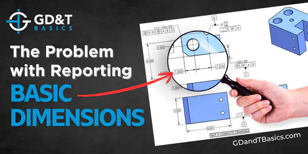
We are frequently asked whether these basic dimensions should be recorded on an inspection report. The answer to this question is, “no.” We will illustrate the problems with reporting basic dimensions using the example of the part shown in Figure 1, below.
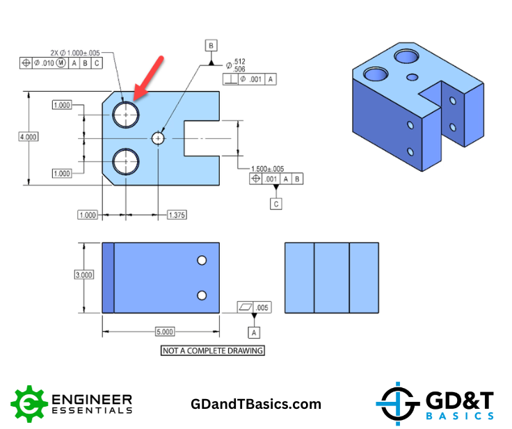
Figure 1: Part drawing with basic dimensions locating 2 bore holes from the Datum Reference Frame
Take a look at the hole shown in the top view of the part in Figure 1, indicated by the red arrow. The theoretically perfect position of this hole is called out using basic dimensions. The positional tolerance of the hole is controlled through the feature control frame. The feature control frame for this hole tells us that the hole has a diametrical position tolerance of 0.01 at Maximum Material Condition in reference to datums A, B, and C. The datums created by the datum features referenced in the feature control frame are indicated in red in Figure 2. Because the position control refers to the datum reference frame ABC, this hole would first be controlled perpendicularly to datum feature A (the bottom surface of the part), then locationally to datum feature B (the small hole in the center of the part), then lastly, to datum feature C (the midplane of the slot).
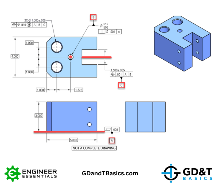
Figure 2: Datum Features A, B, and C
Because the datum reference frame was set up to mimic the part’s functional requirements, inspecting the part against the datum reference frame should ensure that only functional parts will pass inspection.
Reporting Basic Dimensions will not give you the full picture
So, why should we not record basic dimensions on an inspection report? In the example above, there are several basic dimensions that could locate the hole. Which would you choose? Would you measure it from the side of the part (1.000”) or from the center of the small hole (1.375”)?
Additionally, what if the hole isn’t exactly perpendicular to the bottom surface, as illustrated in Figure 3? If you took a measurement from the side of the part to the top of the feature, it would be different than the measurement taken from the side of the part to the bottom of the feature. Which of those measurements would you report? As you can see, a single set of x,y dimensions is not sufficient to determine whether the feature passes inspection.
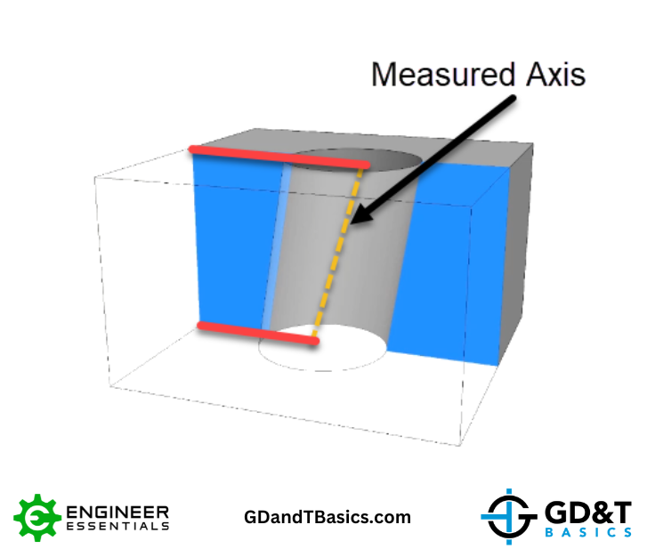
Figure 3: Measurements differ at top and bottom of the hole
What should be recorded on the inspection report?
If basic dimensions give insufficient information to pass or reject the part, what should be recorded? As illustrated in Figure 4, the positional tolerance of this hole is a cylinder. If the measured axis of this hole falls within this tolerance zone, the part will pass inspection.
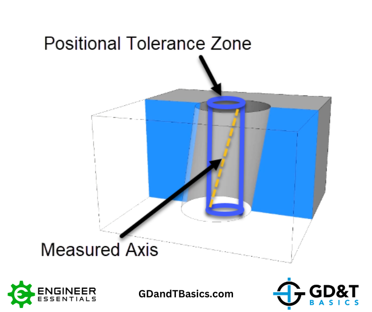
Figure 4: Cylindrical Positional Tolerance Zone
The extremes of the hole’s axis will define the total diametric deviation. This total diametric deviation is what will be recorded on your CMM report. Often the data used to report the deviation can be listed in the report, as well, to give a better perspective of the feature. There is no harm in including extra data in the report, but the total position error as defined by ASME Y14.5 must be reported in order to deem the feature as accepted or rejected.
In summary, basic dimensions do not give sufficient information to pass or reject a feature during inspection, thus should not be reported. A more in-depth discussion of inspecting features defined by basic dimensions can be found in the video below.
The one-page GD&T reference that you will use every day
A visual breakdown of every core GD&T symbol and what it controls, all on one page. Bookmark it. Print it. Actually use it.
Download the Chart