
ASME Y14.5 is an established, widely used GD&T standard containing all the necessary information for a comprehensive GD&T system. This article provides an in-depth look at of the contents, history, and purpose of the standard.
GD&T and Standardization
Geometric Dimensioning and Tolerancing, or GD&T for short, is a language of symbols used to communicate information on technical drawings. In order to communicate accurately in any written language, the writer and the reader must share the same understanding of the symbols and structure of that language. One way to ensure this common understanding is by publishing a document describing the proper use of the language. This concept is known as standardization, and it is just as important for GD&T as any other language. Knowledge of the GD&T standard that your company uses is essential to ensure that drawing information is being interpreted properly.
There are two main standards for Geometric Dimensioning and Tolerancing in use today. The International Organization for Standardization (ISO) publishes a group of standards, known collectively as the Geometrical Product Specifications, or ISO GPS Standards, and the American Society of Mechanical Engineers publishes the ASME Y14.5 Standard. This article focuses on the ASME Y14.5 standard and provides a brief overview of its history, purpose, and content.
ASME AND HISTORY OF Y14.5
ASME is an acronym for The American Society of Mechanical Engineers, a non-profit organization founded to advance, standardize, and disseminate engineering knowledge. Within ASME, Subcommittee 5 of the Y14 Engineering Product Definition and Related Documentation Practices committee is responsible for maintaining and updating the Y14.5 standard.
The modern ASME Dimensioning and Tolerancing standard can trace its roots to the MIL-STD-8 military standard, circa 1949, but it is the 1982 Y14.5 publication that is generally accepted as the first standard to fully incorporate GD&T. Since that time, the ASME standard has been updated in approximately 10-year intervals, most recently in 2018:
1982 – ANSI Y14.5M
1994 – ASME Y14.5M
2009 – ASME Y14.5
2018 – ASME Y14.5
Of companies in the US, Canada, and Australia that have adopted the ASME standard, approximately half are using the 2009 version, and over a quarter still use the 1994 publication. A relatively small percentage of companies are using the 2018 version. At GD&T basics, we use the 2009 standard, and this article is based on that version.
SCOPE AND ORGANIZATION OF THE STANDARD
The ASME website describes the Y14.5 standard as follows:
“The Y14.5 standard is considered the authoritative guideline for the design language of geometric dimensioning and tolerancing (GD&T.) It establishes symbols, rules, definitions, requirements, defaults, and recommended practices for stating and interpreting GD&T and related requirements for use on engineering drawings, models defined in digital data files, and in related documents.”
The standard is intended to provide uniformity in drawing specifications and interpretation, reducing guesswork throughout the manufacturing process. Through this method, Y14.5 aims to improve quality, lower costs, and shorten deliveries wherever mechanical parts are designed or manufactured. It is worth noting that the standard focuses on communicating the intended geometry and does not attempt to address inspection or measurement of geometrical features. Instead, the user is directed to a separate standard for fixtures and gauging principles (ASME Y14.43).
The bulk of the content in the Y14.5 standard is divided into nine major sections with a brief foreword, appendices A through E, and an index. The first three sections of the text contain information on general GD&T principles, with the fourth section pertaining to datum reference frames. Sections five through nine each describe tolerancing of one of the following fundamental categories: Form, Orientation, Location, Profile, and Runout.
SECTION 1 – SCOPE, DEFINITIONS, AND GENERAL DIMENSIONING
This section outlines the scope and intent of the standard, which we have described in detail above. It also provides definitions of key terms used throughout the standard. Additionally, this section outlines basic rules for dimensioning, and it provides a number of examples, illustrating proper dimensioning for many different types of features.
SECTION 2 – GENERAL TOLERANCING AND RELATED PRINCIPLES
Practices for expressing tolerances on linear and angular dimensions are established in this portion of the standard, and modifiers and key principles are introduced. Rule #1, or the Envelope Principle, is described here, as well as Maximum Material Condition (MMC), Least Material Condition (LMC), Regardless of Feature Size (RFS), and other important concepts.
SECTION 3 – SYMBOLOGY
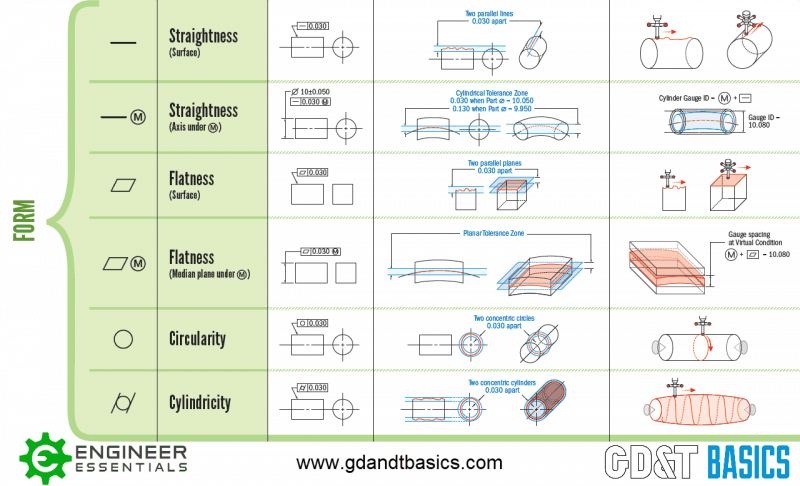
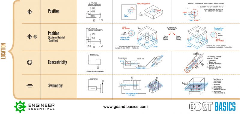
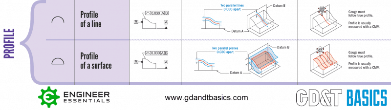
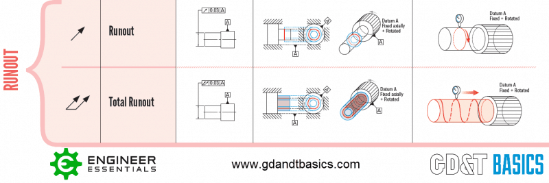
This section standardizes the symbols for specifying geometrical characteristics and other dimensional requirements on engineering drawings. The table below shows symbols for the geometrical characteristics. Many additional symbols are listed and described in this section, including symbols for datums, modifiers, counterbores, countersinks, tapers, and others.
| Type of Tolerance |
Symbol | Location in the Standard |
GD&T Basics Symbol Page |
| Form | Straightness |
5.4.1 | www.gdandtbasics.com/straightness/ |
| Form | Flatness |
5.4.2 | www.gdandtbasics.com/flatness/ |
| Form | Circularity |
5.4.3 | www.gdandtbasics.com/circularity/ |
| Form | Cylindricity |
5.4.4 | www.gdandtbasics.com/cylindricity/ |
| Orientation | Angularity |
6.3.1 | www.gdandtbasics.com/angularity/ |
| Orientation | Perpendicularity |
6.3.3 | www.gdandtbasics.com/perpendicularity/ |
| Orientation | Parallelism |
6.3.2 | www.gdandtbasics.com/parallelism/ |
| Location | Position |
7.2 | www.gdandtbasics.com/true-position/ |
| Location | Concentricity |
7.6.4 | www.gdandtbasics.com/concentricity/ |
| Location | Symmetry |
7.7.2 | www.gdandtbasics.com/symmetry/ |
| Profile | Profile of a Line |
8.2.1.2 | www.gdandtbasics.com/profile-of-a-line/ |
| Profile | Profile of a Surface |
8.2.1.1 | www.gdandtbasics.com/profile-of-a-surface/ |
| Runout | Circular Runout |
9.4.1 | www.gdandtbasics.com/runout/ |
| Runout | Total Runout |
9.4.2 | www.gdandtbasics.com/total-runout/ |
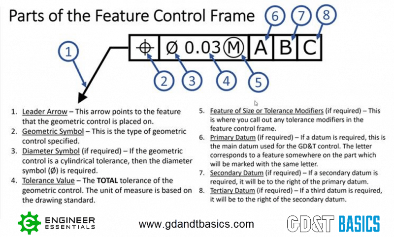
This section also introduces the feature control frame concept. The feature control frame is the rectangular box that surrounds symbols, tolerance values, modifiers, and datum references to create a geometrical tolerance.
SECTION 4 – DATUM REFERENCE FRAMES
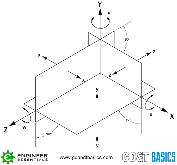
Rules for selecting and referencing datum features are discussed at length in this section, with numerous examples. A datum is a theoretically exact point, line, or plane. In GD&T, one or more datums are established and other features are specified in relation to them. Without a datum reference, a part can move in three spatial directions or rotate about three different axes. These six movements are known as degrees of freedom. Referencing a part to datums can constrain these degrees of freedom.
SECTIONS 5 THROUGH 9 – TYPES OF TOLERANCES AND GEOMETRIC CHARACTERISTICS
Each of these sections covers one of the five fundamental types of tolerances. Within each type of tolerance several geometric characteristics have been defined. Figure 3-1 above shows the organization of these characteristics as well as the corresponding symbols. For more on any of the geometric characteristics, click on the embedded link.
SECTION 5 FORM
This section explains how to properly state tolerances for straightness, flatness, circularity, and cylindricity. These tolerances are used where size tolerances don’t provide sufficient control of the part geometry. Form tolerances are not applicable to datums.
SECTION 6 – ORIENTATION
Angularity, perpendicularity, and parallelism are the three orientation relationships. These tolerances are used to control rotation of a feature relative to a datum. They cannot be used to control location.

SECTION 7 – LOCATION
Position, concentricity, and symmetry are the three types of location tolerances. These are used to control location of features in relation to each other or relative to a datum.
SECTION 8 – PROFILE
A profile is defined as the outline of a surface. There are two types of profile tolerance – profile of a surface, and profile of a line. The profile of a line tolerance controls the shape of a surface relative to a pre-defined ideal cross section of that surface. In this case, the ideal, or “true”, profile can be defined as a two-dimensional shape. The profile of a surface tolerance is used to control the shape of a surface relative to an ideal, or “true”, three-dimensional surface. The standard states: “A digital data file or an appropriate view on a drawing shall define the true profile”. Depending on the profile shape and datums referenced, profile tolerances can control size, form, orientation, and/or location.
SECTION 9 – RUNOUT
Runout is a tolerance used to control variation in a surface when it is rotated about a datum axis. The surface can be either parallel or perpendicular to the datum axis. Circular runout is the term used to indicate that the runout tolerance applies only to a single surface, while the term total runout indicates that the tolerance applies to all surfaces with rotational symmetry about the datum axis.
APPENDICES
Appendices A through E contain additional information. For example, Appendices A and D provide a log of changes from the previous version of the standard and a summary former procedures that are no longer part of the standard. Appendix B presents formulas and definitions describing the fit of mating parts, while Appendix C details how to draw GD&T symbols and cross-references them to their ISO counterparts. Finally, Appendix E contains flow charts to help the user develop geometric constraints that best describe design intent.
KEY TAKE-AWAYS
Geometric dimensioning and tolerancing is used to communicate detailed information on technical drawings. Standardization of GD&T and knowledge of those standards is crucial to ensure that the design intent is communicated properly. ASME Y14.5 is an established, widely used GD&T standard containing all the necessary information for a comprehensive GD&T system.
- The ASME Y14.5 standard establishes symbols, definitions, and rules for geometric dimensioning and tolerancing.
- The purpose of the standard is to ensure clear communication of detailed information throughout the design and manufacturing process for mechanical parts.
- Four versions of the standard have been published, and the 2009 version is the most widely used.
- The standard is organized in nine parts, with details of the geometrical characteristics in parts five through nine.
Need an Overview of the ASME Y14.5 2009 and 2018 Standard?
Check out our free ASME Y14.5 2009 vs. 2018 Comparison Chart
DOWNLOAD NOW
Thank you for posting this , it gives me total basic undestanding of GD&T.
This is an excellent website, I gain a lot of knowledge regarding gd&t.
Thank you for such an amazing content
Well done and clear understanding of how GD&T language works.
This information was useful having a high didactic level of presentation to get a good understanding of how GD&T works. Appreciate your effort!
This information was very useful!