
What is a Datum Reference Frame?
Datums are used in Geometric Dimensioning and Tolerancing drawings to create a reference system for inspecting a manufactured part. This reference system is called a Datum Reference Frame (DRF).
Datums are derived from datum features. Datum features are real, tangible features on a part and are usually important functional surfaces. Datums are the theoretically exact points, lines, axes, etc. that are derived from the datum features and are simulated by measurement equipment. Datum features are the real features of a part that will be physically measured.
The datum reference frame is the coordinate system created by the datums specified within a feature control frame. A datum reference frame sets up the framework that this geometric control will reference from. Other feature control frames that list the same datums with the same order and the same modifiers will also be inspected to this datum reference frame. This is known as simultaneous requirements.
Importance of the Datum Reference Frame in Design
The datum reference frame must lock down all degrees of freedom (DOF) necessary for the part. This generally means that all six degrees of freedom in a coordinate system must be locked down.
The order of the datum features being referenced in a feature control frame is important because it will dictate which features take precedence when locking down the datum reference frame for inspection.
If possible, datum features should be selected in the order that the part would assemble in real life. Lower precedent datums only control the degrees of freedom not already controlled by higher precedent datums.
When designing a part, it is crucial that the datum reference frame mimics the part’s functionality.
Let’s look at the example in Figure 1. In the part drawing below, we will take a look at the datum reference frame being created for the position callout indicated by the red arrow. The feature control frame for this callout references datum features A, B, and C.
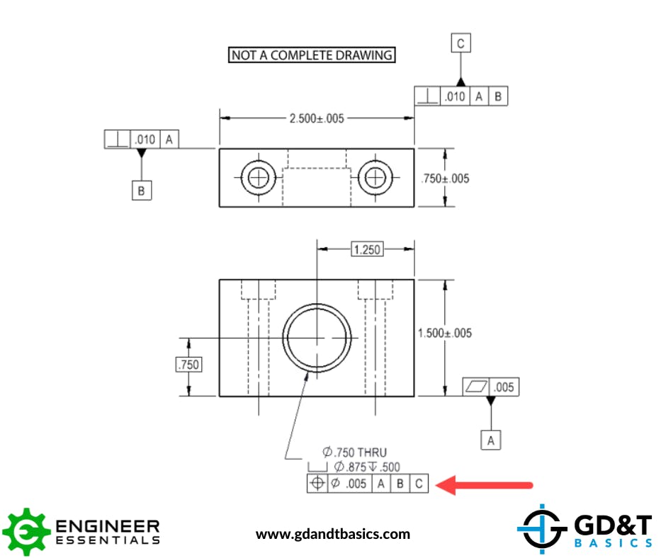
Datum Feature A is the bottom surface indicated on the front view of the drawing that is being controlled by flatness. Because of how the datum feature symbol is placed, we know that it is referencing the surface which results in a planar datum. (For more information regarding Datum Feature Symbol placement, see our Datum Feature Symbol page.)
Datum Feature B is the back surface indicated on top view of the drawing. It is being controlled with perpendicularity back to Datum A. As this datum feature is also a surface, it will also result in a planar datum.
Datum Feature C is the right surface indicated on the top view of the drawing, and it is also being controlled with perpendicularity. However, it is being controlled in reference to Datum A first, then Datum B. This datum feature is also a surface, resulting in another planar datum.
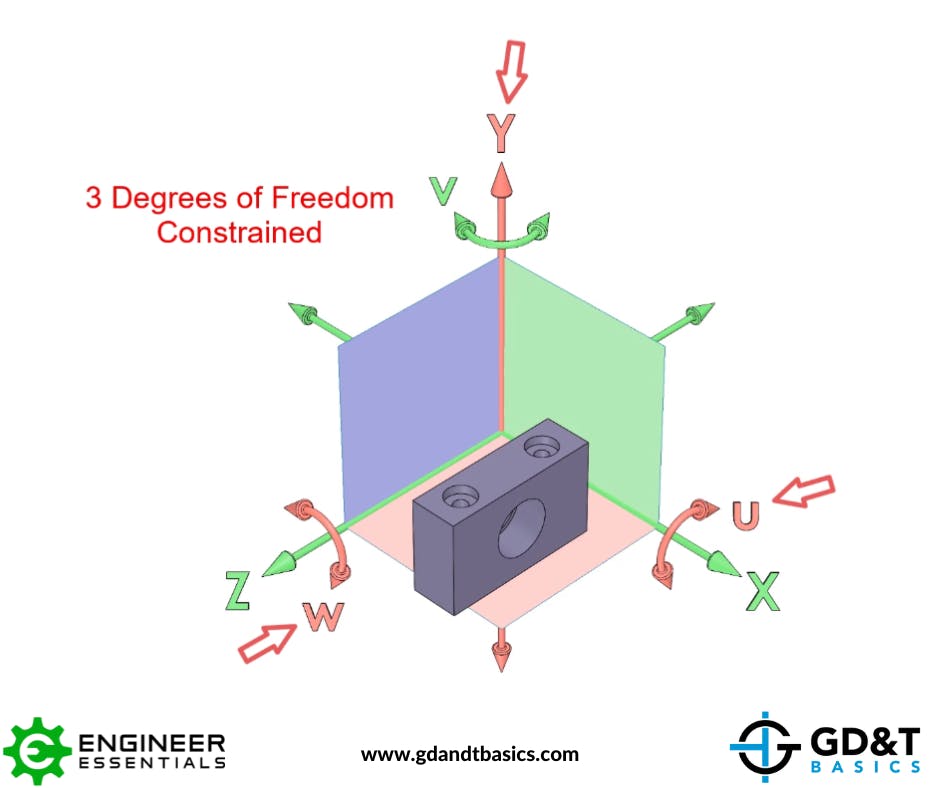
This resulting datum reference frame locks down all 6 degrees of freedom using three mutually orthogonal planar datum features. Datum A locks in three degrees of freedom (one translation: Y, and two rotations: u & w), as shown in Figure 2.
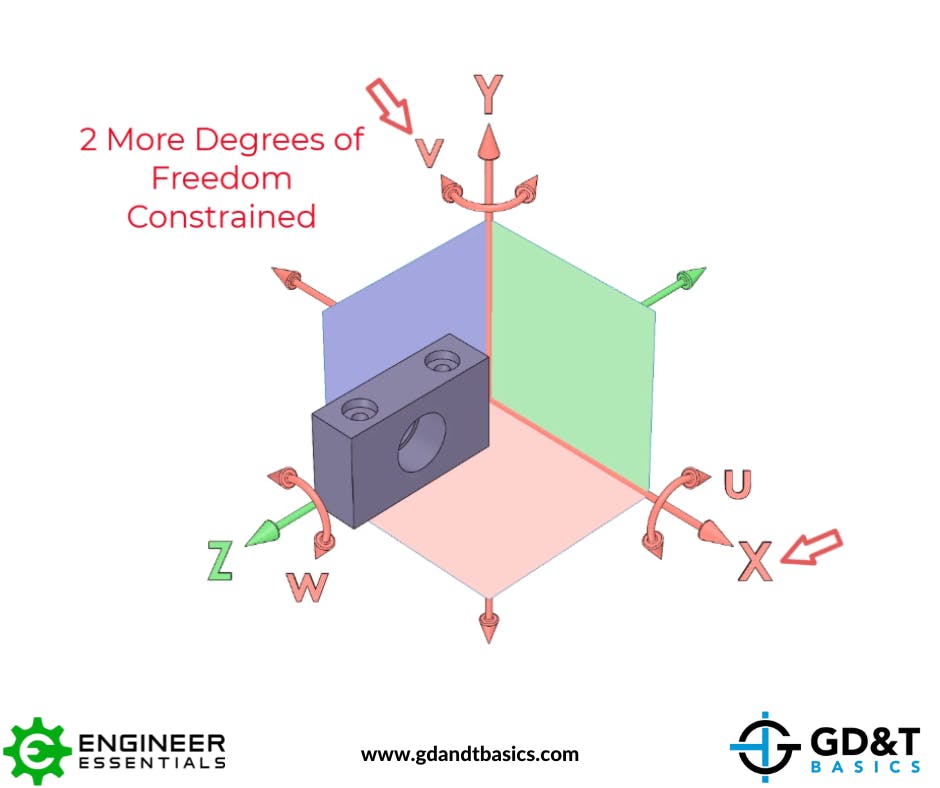
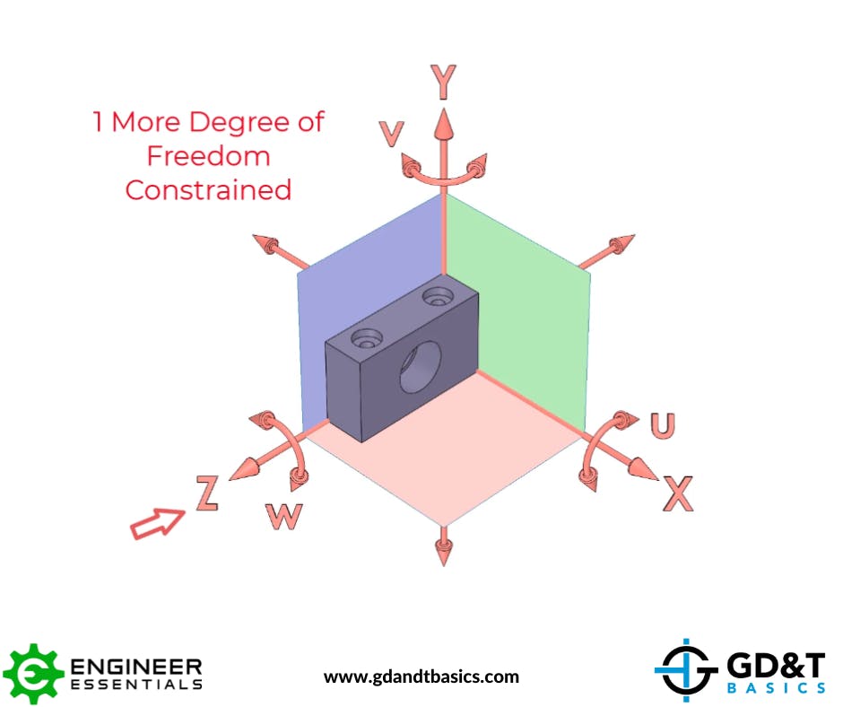
Datum B then locks down two more degrees of freedom (one translation: X, and one rotation: v), as shown in Figure 3. This leaves only one degree of freedom still open.
Finally, Datum C locks down this last degree of freedom (translation: Z), as shown in Figure 4.
Inspecting a Part using the Datum Reference Frame
The manufactured part will be inspected against the datum reference frame. Because the datum reference frame was set up to meet the functional requirements of the part, and Inspection measures the part against the datum reference frame, this ensures that only functional parts will pass inspection.
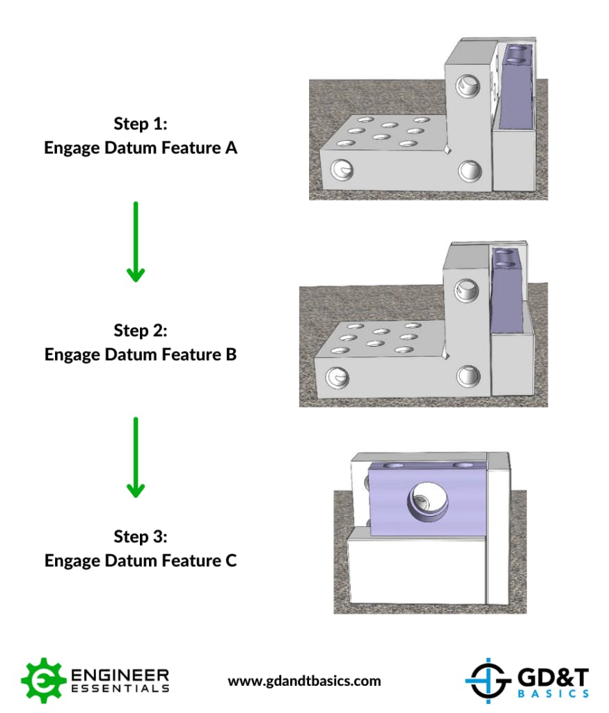
To inspect the part above, we engage Datum Feature A, then B, then C with simulated datums. (Datums are simulated by measurement equipment such as granite slabs, gage blocks, and gage pins, and computer simulated planes.)
We will go through the same process as above for constraining the manufactured part to the simulated datums to inspect the part. We will first engage Datum Feature A with the datum simulator, then Datum Feature B, and lastly, Datum Feature C. This process is illustrated in Figure 5.
Note that any other features that utilize this same datum reference frame MUST be measured before disengaging the part from this setup. This will satisfy the simultaneous requirements mentioned earlier.
For a more in-depth discussion of Reference Control Frames, check out the video below. In this video, Jason explains Datum Reference Frames and how they are used to ensure that the manufactured part will meet its functionality requirements. The example in this article of a datum reference frame created from three mutually orthogonal planar datum features is discussed, as well as how to handle datum features that are features of size, rather than planar.
Be The Go-To Engineer at Your Company
Learn GD&T at your own pace and apply it with confidence in the real world.
VIEW TRAINING OPTIONS