

What is a tolerance? If you take a look at an engineering drawing, you will notice that there are always limits, or tolerances, placed on a dimension. Why does the designer do this?
When a part is designed, the CAD model is designed exactly how we want the part to be. It is designed as a perfect part. However, perfect parts don’t exist in reality. Manufacturing a perfect part is unattainable for several reasons, such as:
- Improper tool usage (worn tools)
- Machining errors (poor machine maintenance)
- Programming errors (feeds and speeds)
- Material stresses (springback)
- Inspection methods
- Employee skill level
- Environmental conditions
- etc.
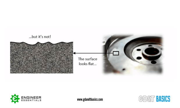
Even a part that looks to be perfect at a macro level will reveal imperfections at a micro view. Take the part in Figure 1, for example. The machined surface looks flat, but if you use a profilometer to measure the surface roughness, we would immediately see that the surface is not actually flat. You may even be able to feel that the surface is not flat by running your fingernail across it.
Does this mean that the part must be scrapped? Is there a level of imperfection that will still allow the part to function as designed? We dictate how much variation we can accept by using tolerances. A tolerance is the acceptable range of dimensional variation that still allows for proper function. This variation defines the maximum and minimum limits for the dimensions.
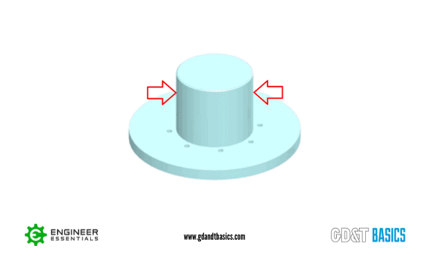
Let’s look at another example. Figure 2 shows a CAD model of a part with a shaft. Even though the CAD model is perfect, we know that the diameter of the shaft will not be perfect. We need to apply a tolerance that will control the diameter of the shaft so that we can ensure that it will function properly when it gets placed into its assembly or final operating conditions.
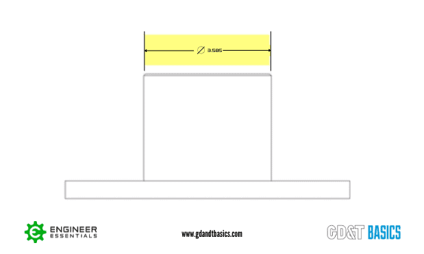
To control the diameter of this shaft, we start by showing the perfect, or ideal dimension, as shown in the drawing in Figure 3. This dimension, 3.585, is the dimension that the CAD model was designed to.
We also need to show what variation in this dimension is acceptable. We do this by adding limits (tolerances) to the dimension. These limits indicate how much the dimension can vary while still maintaining the functionality of the part. Figure 4 shows four different ways that the tolerance for this diameter could be shown on a drawing.
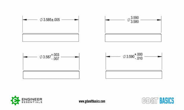
In summary, tolerances are maximum and minimum limits placed on a dimension that indicate the acceptable amount of variation that will still allow for proper function of the part. In upcoming articles, we will dive deeper into why tolerances are used and how they are defined, including the tolerancing methods shown in Figure 4.
Interested in Learning More About Tolerances and Engineering Prints?
Check out our Print Reading and Tolerances Course
LEARN MORE