
Surface finish can be a confusing subject, especially when it comes to units or the difference between Ra and Rz. In this article, we will provide a broad overview and answer some of the most commonly asked questions…
What is Surface Finish?
Surface finish is the term used to describe the texture of a surface, and it is sometimes used interchangeably with the term surface texture. Requirements for surface finish are frequently found on technical drawings for mechanical parts, particularly where parts fit together tightly, move against each other, or form a seal. The American Society of Mechanical Engineers (ASME) has published the Y14.36M Surface Texture Symbols standard, which illustrates the proper specification and use of surface texture symbols on technical drawings. ASME also publishes the B41.6 Surface Texture Standard, which contains definitions and measurement methods for surface finish.
Surface finish is composed of three distinct elements – roughness, lay, and waviness (See Figure 1 below). However, it is not uncommon in machine shops for the term surface finish to be used to describe only surface roughness. Roughness is the most commonly specified aspect of surface finish, however, before we get into the details Surface Roughness, let’s discuss these three elements that make up Surface Finish.

Lay
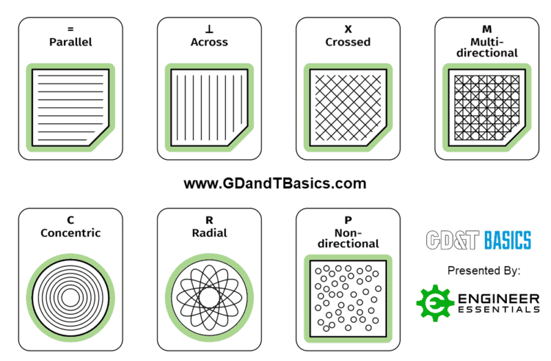
Lay is the term used to describe the dominant pattern on a surface and the orientation of that pattern. Lay is generally produced by the manufacturing process and can be parallel, perpendicular, circular, crosshatched, radial, multi-directional, or isotropic (non-directional). We will discuss the symbols and interpretation of lay in the Symbols section below.
Waviness
Waviness is the term used for the most broadly spaced surface finish variations. These periodic imperfections in the surface are larger than the roughness sampling length but small, short, and regular enough that they are not considered flatness defects. Common causes of surface waviness include warping from heating and cooling, and machining defects from chatter or deflection.
Waviness is measured over an evaluation length, and a waviness profile for that length is generated. The waviness profile does not include any irregularities in the surface due to roughness, flatness, or form variations. Waviness spacing (Wsm) is the peak-to-peak spacing of the waves, while the wave height is defined by the average waviness (Wa) or total waviness (Wt) parameters. Waviness requirements are less common than roughness requirements, but they can be important for certain parts, such as bearing races or sealing surfaces.
Surface Roughness
Surface roughness, frequently shortened to roughness, refers to small irregularities in surface geometry. Roughness is the most commonly specified, measured, and calculated aspect of surface finish, and many people use the term “Surface Finish” to only describe roughness.
Measurement of Roughness
Surface roughness is typically measured perpendicular to the lay direction by an instrument known as a profilometer (shown in Figure 2 below). The profilometer generates a graph showing variations in surface height with changes in position. This graph is known as the measured surface profile, and an example is shown below. The measured profile will show not only roughness, but also any wave and flatness defects that may be present. To examine only roughness, we must remove the wave and flatness defects from the profile.
Without smoothing the profile, the mean line (shown in Figure 2 below) will represent surface height variation due to waviness and flatness defects. Since we are not interested in variation due to these items, we need to measure the profile with the mean line straightened. To do this, first, we average the surface height over intervals less than the waviness spacing, but greater than the roughness spacing to smooth out the larger waviness. This new, straighter line is known as the surface roughness profile (Figure 3).
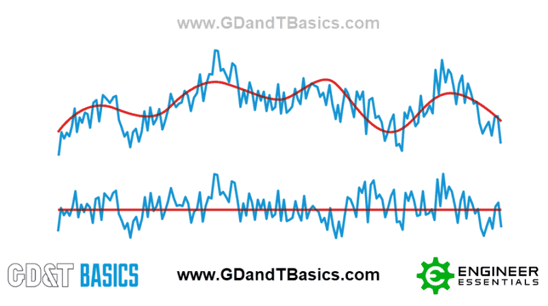
Line 1: Measured profile & mean line – Includes wave and flatness variations
Line 2: Roughness profile & mean line, wave and flatness variations filtered out
Roughness Parameters & Calculations
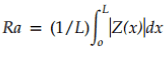
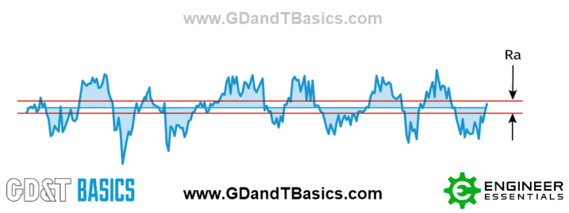
On technical drawings, roughness is simplified to a numerical value that represents characteristics of the roughness profile. The most frequently specified roughness parameters are Ra and Rz. Ra, or average roughness, is typically used in the United States, while Rz, or mean roughness depth, is commonly used internationally. Ra is defined as the average variation of the roughness profile from the mean line. In mathematical terms, this is the integral of the absolute value of the roughness profile, divided by the profile length. Because of this averaging, the Ra value is lower than the actual height of the roughness variations.
To calculate Rz, the roughness profile is divided into five equal lengths. The height difference between the highest and lowest point in each of the five sections is known as the total roughness, or Rt, for that section. Rz is the average of the five Rt values. The calculated Rz value is approximately the height of the most severe roughness variations.
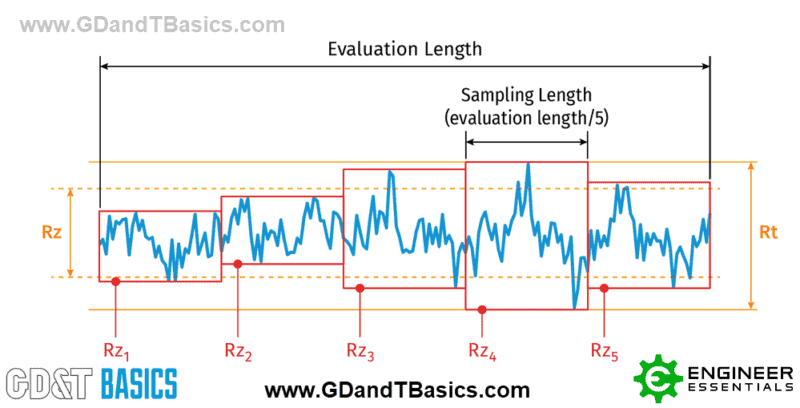
Since Ra represents average values, and Rz is based on maximum values, Rz is almost always greater than Ra. The difference between the two parameters will depend on the uniformity of the roughness profile. If one value is known, it is possible to estimate a maximum for the other, but this approximation should not be used for critical applications. As a rough rule, if only Rz is known, Ra can be approximated by dividing by a factor of 7.2. If Ra is known, the value of Rz for the same surface can be up to 20 times higher and a little more difficult to approximate.
Roughness Units of Measurement
The unit used in the United States for roughness measurement is micro-inches. This unit represents one millionth of an inch, and it is typically written µ in. The corresponding international (SI) unit is micrometers, or microns for short. This unit represents one millionth of a meter, and it is written as µm or um. Just as one meter is 39.37 inches in length, one micrometer is equivalent to 39.37 micro-inches.
Symbols
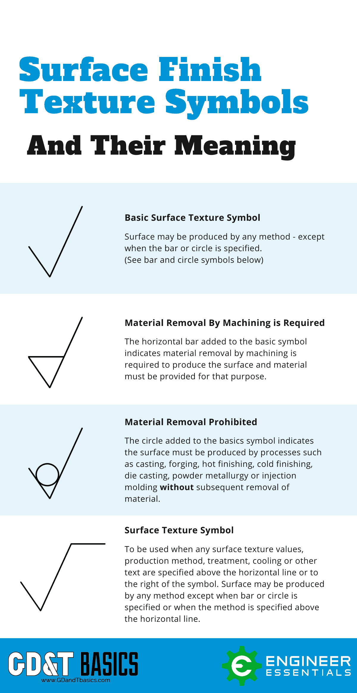
The basic surface finish symbol is a check mark with the point resting on the surface to be specified. Variations of this symbol provide additional instructions as described in the table below.
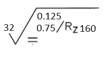
Numbers near the basic surface finish symbol are used to provide different surface finish parameters. The location of the number in relation to the symbol determines which parameter is indicated. The letters in the figure below show the proper location for each parameter according to the ASME Y14.36M Standard.
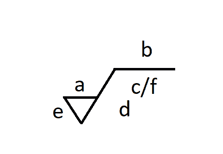
Where a represents the average roughness value (Ra), and b represents the production method, coating, note, or other additional information. The letter c provides the roughness sampling length in millimeters or inches, while d gives the direction of the surface lay. The value of e indicates a minimum material removal requirement in millimeters. Finally, if an alternate surface finish parameter is provided, the parameter symbol and value are provided in location f (ie: Rz 0.4).
The seven possible lay directions are indicated in the table below.
In the example below, Ra is specified to be no greater than 32 µ in. over an evaluation length of 0.125 inches. Rz is required to be no greater than 160 µ in. over an evaluation length of 0.75 inches. The lay direction is parallel to the drawing plane of view where the symbol appears.
Practical Considerations
Surface finish is highly dependent on the process used to manufacture the part, and very smooth surface finishes usually require additional processing such as grinding or polishing. Since additional processing will add additional cost, it is important that the engineer or designer does not impose unnecessarily low roughness requirements. Where possible, the roughness specifications should be within the limitations of the primary manufacturing process.
Within the capability range of the equipment, some manufacturing processes allow a degree of control over the surface finish. For example, when milling or turning, shallow cutting depths and slow feed speeds typically provide smoother finishes, while deeper cuts and faster speeds provide rougher finishes. Cutting tool wear can also affect surface finish. The chart below shows the range of surface roughness values typically produced by various manufacturing processes.
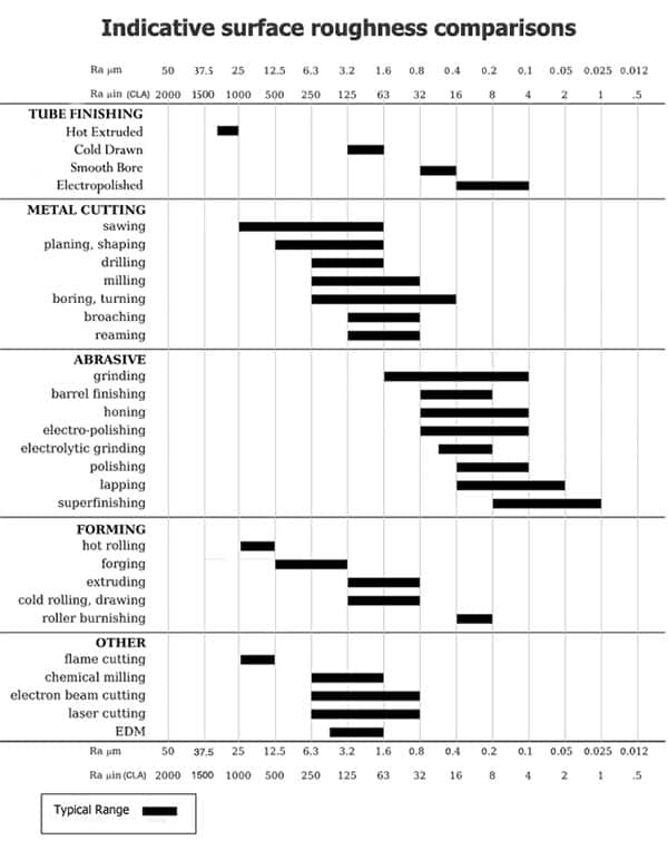
Picture Courtesy of Emok – Wikipedia
Key Take-Aways
- Surface Finish consists of waviness, lay, and roughness, but it is common for only roughness to be specified on technical drawings.
- Ra is average roughness, and it under-estimates surface height variations.
- Rz is mean roughness depth, and it approximates the size of the most severe surface height variations.
- Ra < Rz in most cases. General conversion: 7.2 x Ra = Rz (rough estimation only)
- It is important to know if roughness is specified in SI units (micrometers) or English units (micro-inches).
- Smoother surfaces are more expensive because more manufacturing processes are required. Therefore, the roughest acceptable finish should be specified to minimize cost.
Interested in Receiving More Engineering Print and GD&T Tips?
We can help!
Click here for information about our GD&T Courses