

When you want to join two objects, but retain the ability to easily separate them, a great choice is to use a threaded connection. To understand the thread requirements on your drawing, you need to know common standard thread information. In this article, we will be discussing thread diameters, threads per inch and thread pitch.
Thread Diameters
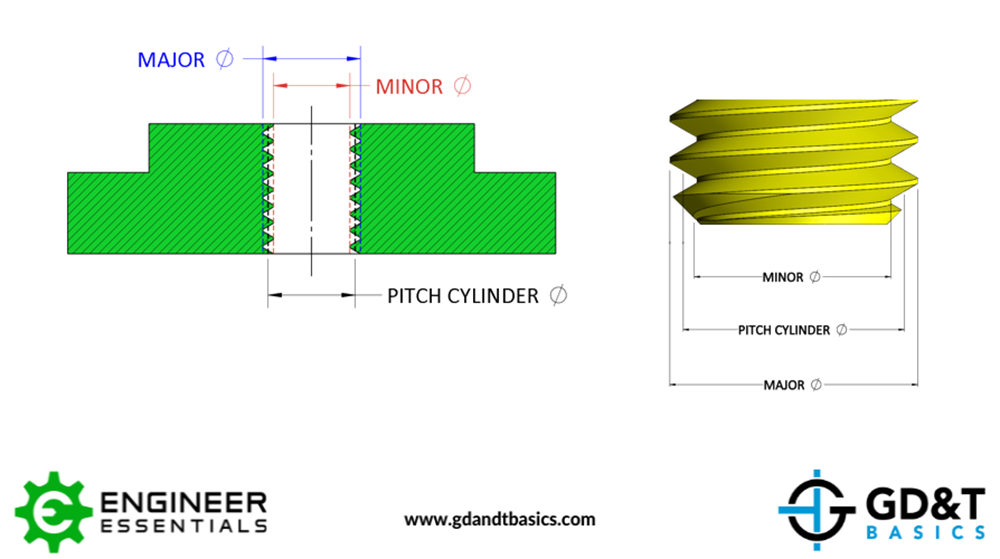
A thread has three diameters: a major diameter, a minor diameter, and a pitch cylinder diameter. This terminology is used for both internal and external threads. The three thread diameters are defined below, and illustrated in Figure 1.
Major diameter: the largest diameter of the thread. On an internal thread, the major diameter is measured from thread root to root. On an external thread, the major diameter is measured from thread crest to crest.
Minor diameter: the smallest diameter of the thread. On an internal thread, the minor diameter is measured from crest to crest. On an external thread, the minor diameter is measured from root to root.
Pitch Cylinder diameter: the effective thread diameter where the thread thickness is equal to the space between the threads. This is also the default diameter that must be used to inspect the location of the threaded feature unless the minor or major diameter is specified.
Pitch cylinder diameter is the diameter used for inspection according to ASME standards. It is the default diameter used for inspection, unless otherwise specified.
Threads Per Inch & Thread Pitch
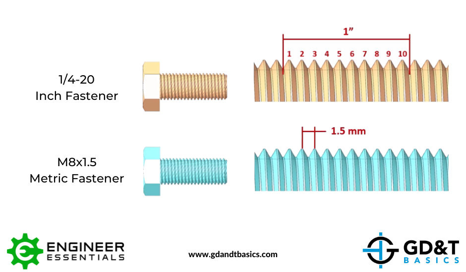
Thread pitch is the distance between two adjacent threads. The larger the distance between threads, the fewer threads you will have across the distance of the total threaded length. This determines whether a thread is considered “coarse” or “fine.” When comparing fasteners of the same nominal thread size, the “fine” threaded fastener will have more threads across a fixed distance than the “coarse” threaded fastener.
Inch threads and metric threads call out the thread type in different ways.
Inch threads are measured as “threads per inch.” This is the number of threads across one inch of the thread length.
Metric threads are measured as “thread pitch.” This is the distance between two adjacent threads.
Coarse pitch threads are the default thread type per both ASME and ISO standards.
Thread Callout Example
When a thread is called out on a drawing, the information will include the nominal size (diameter) and may include either the threads per inch or thread pitch, depending on whether inch or metric threads are being used. If the drawing only calls out the nominal size, we know to choose the coarse pitch thread because that is the default for both ASME and ISO standards.
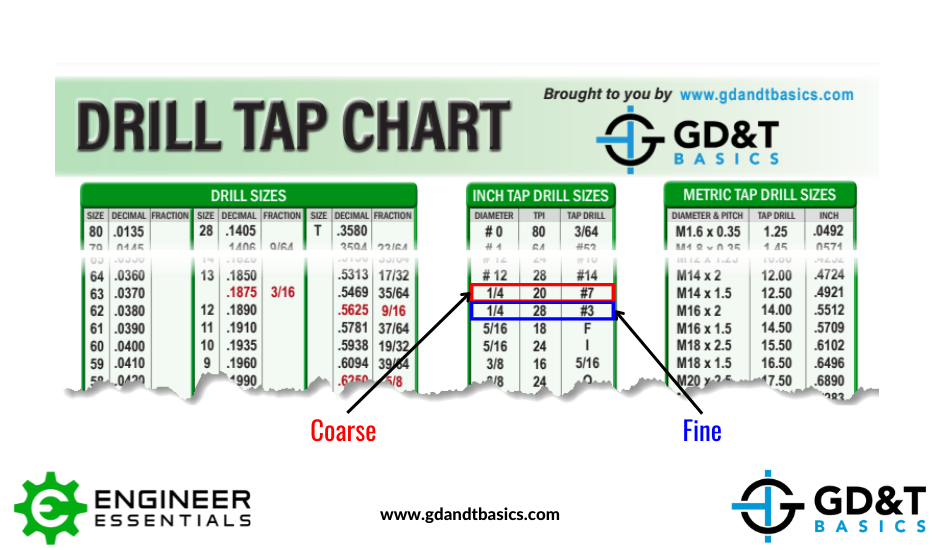
For example, a drawing has a thread callout of ¼”. When we look at a drill and tap chart, we see that there are two options for this size: ¼-20 and ¼-28. This corresponds to a ¼” nominal diameter thread with either 20 threads per inch or 28 threads per inch. The option with fewer threads per inch is the coarse thread. Therefore, we would choose the ¼”-20 option.
Likewise, if a drawing has a thread callout of M8, we see that the Drill & Tap chart includes two thread options: M8x1 and M8x1.25. This corresponds to an 8mm nominal diameter thread with an option of 1mm or 1.25mm thread pitch (distance between threads). The coarse thread is the one with the larger distance between threads, therefore the coarse thread is the M8x1.25 option.
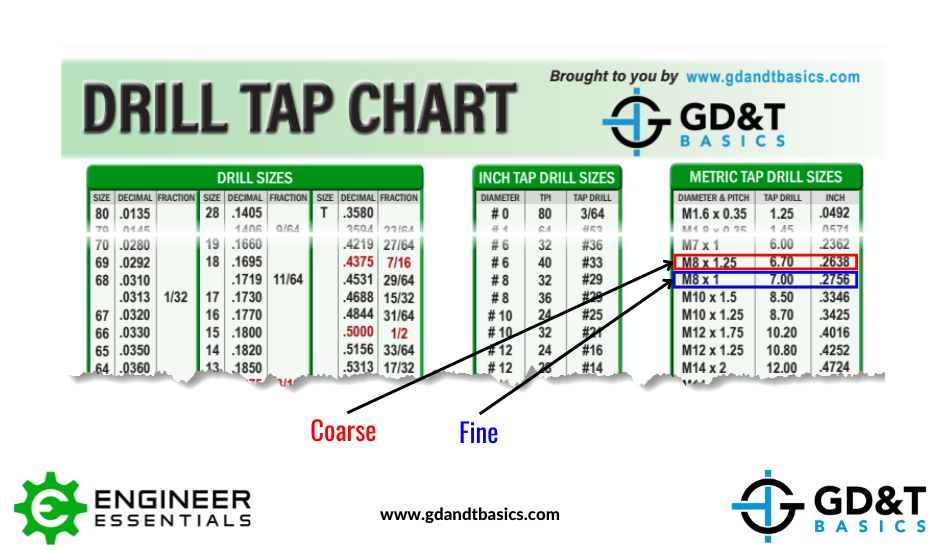
Because both ASME & ISO standards default to the coarse pitch, drill and tap charts will always display the coarse thread first for both inch and metric threads.
Watch our video explanation of thread diameters, thread pitch and threads per inch below:
Be The Go-To Engineer at Your Company
Learn Print Reading and GD&T at your own pace and apply it with confidence in the real world.
GET PRINT READING TRAINING