
To determine when to use Profile of a Surface or Coordinate Dimensioning, let’s first look at what the 2009 ASME Y14.5 Geometric Dimensioning and Tolerancing Standard tells us. Paragraph 2.1.1 was revised to emphasize/encourage the use of basic dimensions in combination with geometric tolerancing as the preferred method of controlling the form, orientation, and location of features. Direct tolerancing methods, limit dimensions, and plus/minus tolerancing should only be used to control the size of features. The ASME standard further recommends avoiding use of plus/minus tolerances on dimensions to locate features of size and surface features.
This means that we should use Position tolerancing for controlling features of size and the Profile of a Surface control for locating and orienting all surface features. Profile of a Surface always controls form as well.
To further explore this topic, let’s consider the example of a thick rectangular plate. The plate has a rectangular cut-out in the center that extends through the thickness of the plate. The corners of the cut-out have a radius. Datum A is the back broad surface of the plate, and datums B and C are the bottom and left edges, respectively.
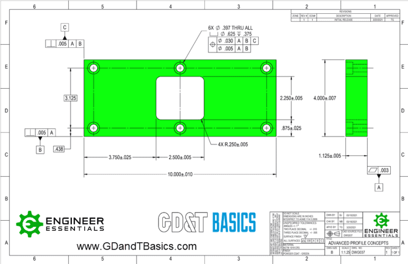
First, let’s consider size, location, orientation, and form of the rectangular cutout window using coordinate dimensioning. Height and width of the opening are established by coordinate dimensions with plus/minus tolerance of 0.005”. Size of the radius applied to the opening corners is also called out as a coordinate dimension with plus/minus tolerance of 0.005”. Note that size is also controlling form due to Rule #1.
Location of the opening is established from datum features B and C using coordinate dimensions with plus/minus tolerances. Note that the coordinate dimensions do not reference the datum, but the datum features, meaning the actual surface of the part. To properly inspect the location of the opening, we must use calipers or a scale to compare points on the two features. Using a datum simulator such as a granite block would be a better method, but is not consistent with the tolerancing used in this case.
No orientation tolerances are called out on the print, but we can refer to the drawing title block to find the default tolerances. Angle tolerances are plus or minus 1 degree. This means that to properly inspect the part, we must inspect the angles of each surface of the cutout in each dimension, or at least do some trigonometry to determine if our measurements are within tolerances.
Now, let’s consider the same example using the Profile of a Surface GD&T callout. In this case, the feature control frame references datums A, B, and C, with a tolerance of 0.005”. Note that the “All Around” symbol is applied here, meaning that the entire surface of the opening is considered together as one feature. Also, note that basic dimensions are used for location and size of the opening. The red lines in the image below highlight the tolerance zone created by this callout.
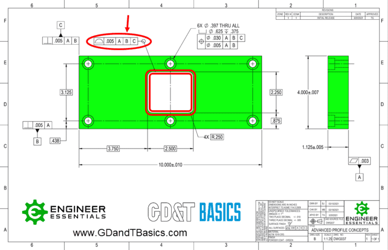
Size of the opening is given by the basic dimensions, but size tolerance is provided by the Profile of a Surface constraint. Form is also controlled by this tolerance, as each point must be within the tolerance zone, which is plus or minus 0.0025” from the basic dimension.
The feature control frame for Profile of a Surface references datums A, B, and C, respectively, and in this case, we know that each part of the surface is located with respect to these datums. Note that the datums are referenced, so inspection can be accomplished by using datum simulators such as a granite block and/or 90-degree fixture.
Finally, the orientation of the cutout surfaces is controlled with respect to the datums. Inspection of perpendicularity or parallelism of each surface with respect to a datum and should be in the order that datums are referenced. Again, this allows us to simplify the inspection process by using datum simulators.
In conclusion, we can use the Profile of a Surface GD&T constraint to comply with ASME recommendations and simplify inspection requirements. Often, methods used to inspect parts drawn with coordinate dimensions are technically incorrect, but applying GD&T can align the print with the inspection methods.
Interested in learning more about Profile Symbols?
Check out our GD&T Courses to learn more!
View GD&T Training