

In this question line video, Brandon discusses Virtual Condition and whether it can apply at Regardless of Feature Size (RFS).
What is Virtual Condition (VC)?
When a feature is controlled with the Maximum Material Condition (MMC) modifier or Least Material Condition Modifier (LMC), a size boundary is created based on the collection of geometric and size tolerances. This boundary is the actual maximum envelope that a part can be within and maintain specification. This is called the Virtual Condition.
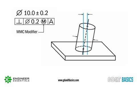
The example in Figure 1 shows a cylindrical part with its size tolerance and feature control frame. It has a size of Ø10.0 +/- 0.2 and a perpendicularity callout with a diameter tolerance of 0.2 at MMC. The virtual condition for this feature would be calculated as follows:
Virtual Condition = Ø10.2 (size at MMC) + Ø0.2 (perpendicularity tolerance) = Ø10.4
As we depart from the Maximum Material Condition, we gain bonus tolerance. (Bonus tolerance is the difference between the actual feature size from the MMC.) So, if the actual feature size was at the least material condition, Ø9.8, we would subtract that from MMC and get a bonus tolerance of 0.4. This 0.4 would be added to the stated Ø0.2 perpendicularity tolerance in the feature control frame and result in a perpendicularity tolerance with a diameter of 0.6.
The benefit of designing at Maximum Material Condition is two-fold. Determining the Virtual Condition gives you the worst-case limits for that feature. It introduces Bonus Tolerance, and it also allows for functional gaging, which can be a huge manufacturing benefit.
What is Regardless of Feature Size (RFS)?
Regardless of Feature Size (RFS) requires no callout on a drawing because it is the default condition for geometric tolerances in GD&T according to Rule #2 in the ASME Y14.5 1994 and 2009 standard. Regardless of Feature Size means that the geometric callout (such as perpendicularity) is controlled independently of the size dimension of the part. RFS is commonly used when the size tolerance and geometric tolerance need to be more tightly controlled, such as the case with press fits and threads. There is no bonus tolerance at RFS.
Virtual Condition and RFS Boundaries
Can Virtual Condition exist at RFS? By definition, Virtual Condition only applies when the MMC or LMC modifier is called out. However, confusion may arise when we look at Virtual Condition compared to RFS boundaries (Inner and Outer Boundary). Figure 2 shows a comparison of Virtual Condition at MMC and boundaries at RFS for the part shown in Figure 1.
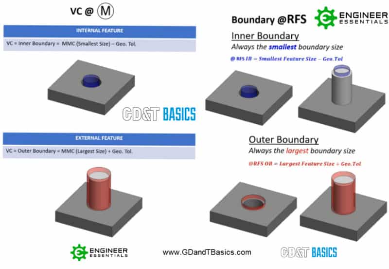
The left side of Figure 2 illustrates the Virtual Condition for an internal and external cylindrical feature designed at MMC. The calculations for the Virtual Condition are shown below:
Virtual Condition (internal feature) = MMC (smallest size) – Geometric Tolerance
Virtual Condition (external feature) = MMC (largest size) + Geometric Tolerance
For an internal feature, the Most Material Condition is the smallest size hole.
The right side of Figure 2 illustrates the inner and outer boundaries of a cylindrical feature at RFS. The inner boundary for a feature at RFS is always the smallest boundary size. The outer boundary at RFS is always the largest boundary size. (Note the usage of “smallest” and “largest” for the size without mention of “MMC” or “LMC”. The calculation for the inner and outer boundaries for a feature at RFS are shown below.
Inner Boundary @ RFS = Smallest Feature Size – Geometric Tolerance
Outer Boundary @ RFS = Largest Feature Size + Geometric Tolerance
Notice that the Virtual Condition at MMC for the internal feature results in the same calculation as the Inner Boundary at RFS. The same is true for the Virtual condition of an external feature compared to the Outer Boundary at RFS. The difference in boundary calculations is only in terminology.
We can also compare Virtual Condition at Least Material Condition (LMC) to RFS boundaries. Figure 3 shows the same cylindrical part at LMC compared to RFS.
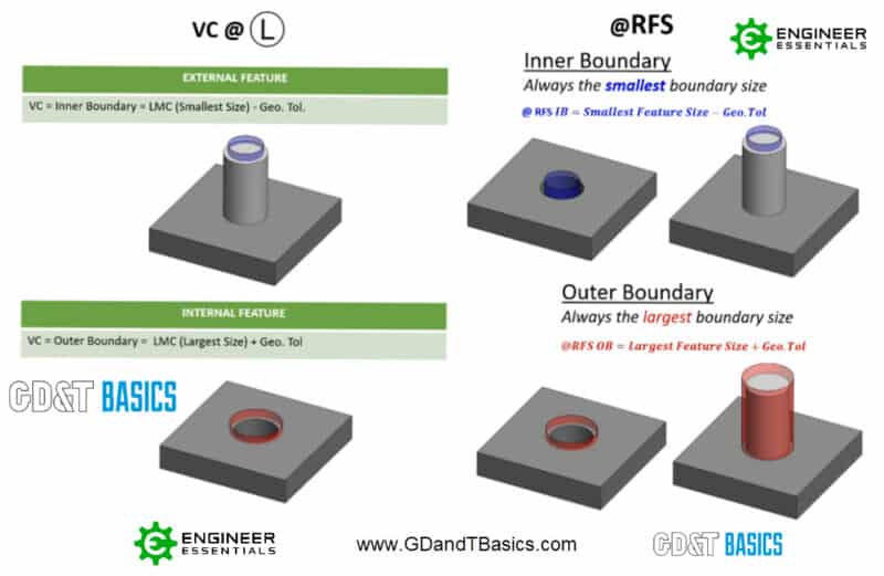
As in the previous figure, the left-hand side of Figure 3 shows the Virtual Condition of a cylindrical feature. In this case, the Virtual Condition is found at LMC rather than MMC. The right side of Figure 3 shows the same boundaries at RFS as in Figure 2.
You can see from Figure 3 that the Virtual Condition of an external feature at LMC is also the same as inner boundary at RFS. Both are calculated using the smallest feature size. Furthermore, the Virtual Condition of the internal feature at LMC is the same as the outer boundary at RFS. In this case, both calculations use the largest feature size.
Difference Between Virtual Condition and RFS Boundaries
By definition, Virtual Condition can only be applied at MMC or LMC, not at RFS. Now that we have compared Virtual Condition and RFS inner and outer boundaries, it may seem that this is untrue, as the boundary calculations are identical. However, there is more to the application of Virtual Condition in Geometric Dimensioning and Tolerancing than simply creating a boundary. You can learn more about the effects of applying Virtual Condition at MMC, including Bonus Tolerance and functional gauging, on our Symbols page for Maximum Material Condition.
The one-page GD&T reference that you will use every day
A visual breakdown of every core GD&T symbol and what it controls, all on one page. Bookmark it. Print it. Actually use it.
Download the Chart