
This video is in response to a question that we received on our question line from Alex. His question is as follows: “Is there a best-practice way to use Position (instead of Symmetry) to control two planar surfaces situated on the sides of a round shaft, by using the round section’s axis as a datum? Since Position for planar features controls the midplane of those features, is the tolerance zone still two planes parallel to that midplane or is it cylindrical since the datum is the long axis of the part?”
To further explore this question, it is helpful to first review our definitions of Position and Symmetry. Position controls the straight center plane (or axis) of the actual mating envelope. As long as the surface form is within the size limit by Rule #1 of Geometric Dimensioning and Tolerancing and the feature meets the Position requirements, your part is in spec. The surface form does not contribute to Position. Symmetry controls the median points of surface elements. The magnitude of the form is not controlled, however, the form/mass distribution on your surface needs to be even to be in specification.
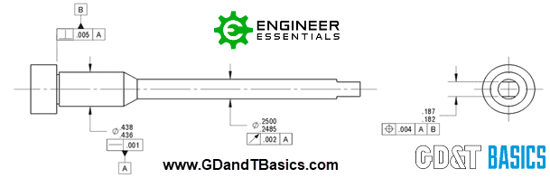
Consider the following drawing of a shaft with two flats on one end:
In this example, using symmetry in place of position for our flats would not be a good idea. Since symmetry considers median points, it will allow large errors as long as the errors are opposite and equal. This means the flats are not required to be parallel to the datum axis or each other. In fact, the flats could be tapered toward or away from each other and still satisfy a symmetry constraint.
The better practice is to use position. In the example drawing above, datum A is the axis of the shaft, and datum B is a surface perpendicular to A. Referencing the position of the two flats in relation to datum axis A constrains four degrees of freedom – two in translation and two in rotation. The reference to datum plane B constrains translation in the third direction. Neither of the datums can constrain rotation about datum axis A. However, we have no other features that would require us to index or constrain rotation of the part in this direction. Therefore, we can consider this a full datum reference frame for the example part.
The position callout in the example above defines the tolerance zone for the midplane of the two flats as two parallel planes 0.004 apart, with the datum axis centered between them.
Returning to Alex’s question, we can definitively state that Position is the preferred callout for this application. In fact, while the 1994 and 2009 ASME Y14.5 standards discourage the use of Symmetry, it has been removed from the 2018 ASME Y14.5 standard and use of this callout is not supported by that standard at all.
Need an Overview of the ASME Y14.5 2009 and 2018 Standard?
Check out our free ASME Y14.5 2009 vs. 2018 Comparison Chart
DOWNLOAD NOW