
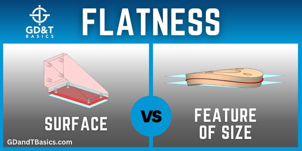
In this video, Brandon discusses the difference between measuring Flatness of a Surface and Flatness of a Feature of Size (FOS).
Flatness of a Surface
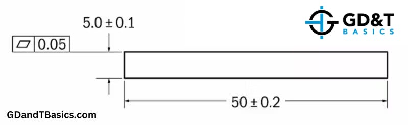
Surface flatness is the type of flatness that most people are familiar with. On a drawing, the flatness callout can point straight to the surface with a leader arrow or be extended out from the surface and away from the feature of size. As you can see in Figure 1, the surface’s flatness requirement is not in line with the size dimension. Noticing the flatness symbol’s placement is critical in determining whether the flatness requirement is for a surface or a feature of size (FOS).
Flatness of a surface is merely defining how flat a surface feature must be and is the condition of being purely planar. The flatness tolerance zone is a 3D tolerance zone, meaning that when you are checking flatness of a surface, you are checking the amount of variation up and down the y-axis over the entire plane. Figure 2 shows the tolerance zone for the surface flatness called out in the drawing in Figure 1.
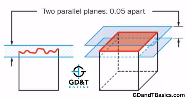
In Figure 2, the surface being measured is shown in red. It is in tolerance if all points on the surface lie within the tolerance zone of 0.05. The cross-section shown in Figure 2 shows that as long as the surface fits between the two parallel planes of the tolerance zone, the flatness requirement is met.
Flatness of a Feature of Size
Flatness of a Feature of Size (FOS) is shown using the same flatness symbol used for a surface’s flatness. (There is only one flatness symbol.) Flatness for a feature of size is indicated on a drawing by having the flatness callout directly in line with the feature of size dimension. As seen in Figure 3, the flatness requirement is placed directly under the size requirement.

Flatness for a feature of size is found by first obtaining the derived median plane of the feature and then checking that the derived median plane is within the allowable tolerance zone. Flatness of a derived median plane (Flatness DMP) is applied to things that we know will have a bow in them, such as a large sheet of metal. It can only be used for flat features of size, such as plates, tabs, and slots.
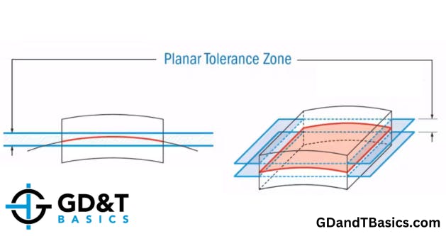
The tolerance zone for flatness of a feature of size is also a 3D tolerance zone. For flatness of a feature to be in tolerance, its derived median plane must fall within the tolerance zone. Figure 4 shows the tolerance zone for the feature of size shown in Figure 3. The two parallel planes shown in blue indicate the tolerance zone, and the derived median plane is shown in red.
Two things to note about flatness for a feature of size (Flatness DMP) compared to surface flatness:
- Flatness, as applied to a feature of size, automatically overrides Rule #1 of Geometric Dimensioning and Tolerancing. (Rule #1 is still in effect for surface flatness.)
- Flatness for a feature of size (Flatness DMP) can be applied Regardless of Feature Size (RFS) or at Maximum Material Condition (MMC). We see this most often at MMC. If it is at MMC, we can use a functional gauge to inspect it. (The MMC modifier can’t be used on surface flatness because there is no MMC of a surface.)
Flatness Measurement Comparison
Surface flatness and Flatness DMP can both be measured using a CMM. Figure 5 illustrates how surface flatness and flatness DMP for our above examples would be found using a CMM.
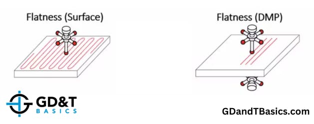
Surface flatness measured by a CMM is shown in the left side illustration of Figure 5. The probe of the CMM measures and collects points on a single surface. For the surface to be in tolerance in our example, all points on the surface must lie between two parallel planes that are 0.05 apart.
Flatness of a Feature of Size (Flatness DMP) measured by a CMM is shown on the right side illustration in Figure 5. The probe measures both sides of the part to establish the derived median points of each cross-section. The points are calculated and added together for a Derived Median Plane based on the internal software calculations of the CMM. The DMP is then compared against the tolerance zone of the two parallel planes that, in our example, are spaced at 0.05 apart. No part of the DMP is allowed to cross the tolerance zone; otherwise, the part will be out of tolerance.
Interested in learning more about GD&T?
Learn GD&T at your own pace and apply it with confidence in the real world.
Click Here For More Information