Tolerance stacks can be a nightmare
When a feature is located relative to other features, the location tolerance of that feature will be affected by the location tolerances of the features that it is dimensioned from. As these tolerances begin to stack up, it can result in unintentionally large location tolerances for your feature, or difficult tolerance calculations, which can cause issues when assembling with mating parts.
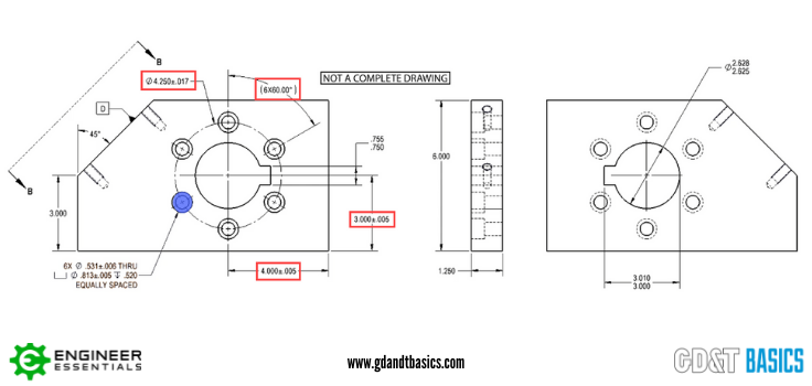
An example of tolerance stack-up on a part is illustrated in the coordinate dimensioned drawing shown in Figure 1.

Let’s say we want to locate the bolt hole (highlighted in blue in Figure 1). The location of this bolt hole is dependent on several items, outlined in red in Figure 1:
- The bolt circle diameter: 4.25 +/-.017
- The bolt hole pattern: 6 x 60.00 deg (with an angular tolerance dependent on how you interpret the drawing)
- The location of the center of the bolt circle: x = 4.000 +/-.005, y = 3.000 +/- .005
As you can imagine, this tolerance stack-up would be a bit tricky to calculate. So how would using Geometric Dimensioning and Tolerancing, rather than coordinate dimensions, avoid this tolerance stack-up situation?
Avoiding tolerance stack-ups with GD&T
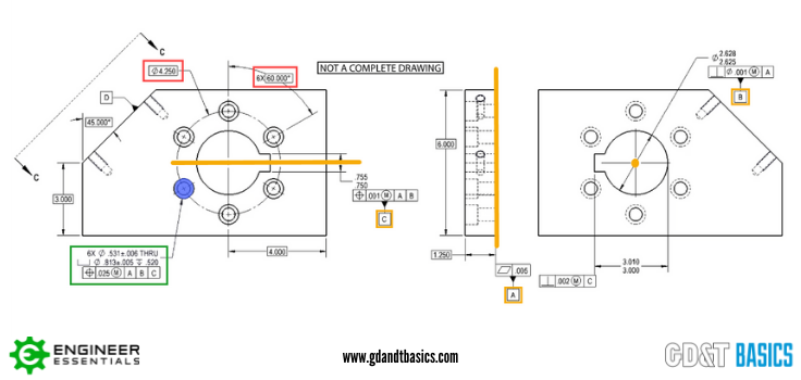
We are going to look at this same part, but now it is dimensioned using GD&T, as shown in Figure 2.

In this drawing, the dimensions for the bolt circle diameter and the bolt hole pattern angle are now shown as basic dimensions, highlighted in red in Figure 2. These dimensions set up the true position of the bolt holes, and there is no tolerance associated with them. The tolerance of the bolt hole location comes into the drawing through the feature control frame for the bolt holes, highlighted in green in Figure 2. The tolerance is a diametric tolerance zone centered on the established true position. This feature control frame includes the position symbol, indicating that it is controlling the tolerance of the position of the bolt holes.
The feature control frame for the bolt holes also references Datum Features A, B, and C, which sets up the Datum Reference Frame for inspecting the part. (The datum reference frame is usually set up to mimic the way that part is assembled.) Datum Feature A is the back surface of the part, Datum Feature B is the bore, and Datum Feature C is the keyway. The datums created by the datum features referenced in the feature control frame are highlighted in yellow in Figure 2. During inspection, the part will be fully constrained to this datum reference frame. Because we are checking the part in respect to the way it will be assembled, this ensures that only a functional part will pass inspection.
As mentioned above, there is no tolerance associated with basic dimensions – they relate back to the datum reference frame. Because there is no tolerance associated with these dimensions, the only tolerance for the location of the bolt holes comes from the position control through the feature control frame for the bolt holes. Therefore, tolerance stack on this part for location is avoided by using GD&T.
Using the appropriate datum features to set up your locational tolerances also helps reduce the number of tolerance calculations that would be required for a full assembly of parts.
For a more in-depth look at this example of how tolerance stacks can be avoided using GD&T, check out the video below.
Overwhelmed by the Complexity of GD&T?
Learn GD&T at your own pace and apply it with confidence in the real world.
Get Your GD&T Training
