
Definition:
A feature control frame is used in Geometric Dimensioning and Tolerancing to describe the conditions and tolerances of a geometric control on a part’s feature. The feature control frame consists of four main pieces of information:
- GD&T symbol or control symbol
- Tolerance zone shape and dimensions
- Tolerance zone modifiers: material condition modifiers, projections…
- Datum references (if required by the GD&T symbol)
This information provides everything you need to determine how the geometrical tolerance needs to be interpreted and how to measure or determine if the part is in specification.
Example Frames:

Parts of the Feature Control Frame
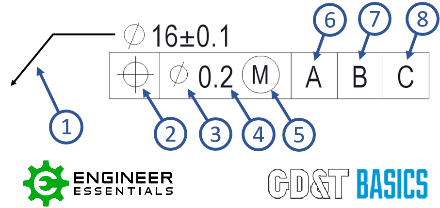
- Leader Arrow – This arrow points to the feature that the geometric control is placed on. (Extension Line or no line as shown)
- Geometric Symbol – This is where your geometric control is specified. See our page on GD&T symbols for a description of each symbol.
- Diameter Symbol (if required) – If the geometric control is a diametrical tolerance, then the diameter symbol (Ø) will be in front of the tolerance value.
- Tolerance Value – The TOTAL tolerance of the geometric control. The unit of measure is based on the drawing standard.
- Feature of Size or Tolerance Modifiers (if required) – This is where you call out any tolerance modifiers in the feature control frame. See the Modifiers section of the GD&T Symbols page for further clarification on these features.
- Primary Datum Feature Reference (if required) – If a datum is required, this is the main datum feature used for the GD&T control. The letter corresponds to a feature somewhere on the part which will be marked with the same letter. This is the datum that must be constrained first when measuring the part. Note: The order of the datum is important for measurement of the part.
- Secondary Datum Feature Reference (if required) – If a secondary datum is required, it will be referenced to the right of the primary datum feature reference. This letter corresponds to a feature somewhere on the part which will be marked with the same letter. During measurement, this is the datum fixated after the primary datum.
- Tertiary Datum Feature Reference (if required) – If a third datum is required, it will be referenced to the right of the secondary datum feature reference. This letter corresponds to a feature somewhere on the part which will be marked with the same letter. During measurement, this is the datum fixated last.
Reading the Feature Control Frame
The feature control frame forms a kind of sentence when you read it. Below is how you would read the frame in order to describe the feature.
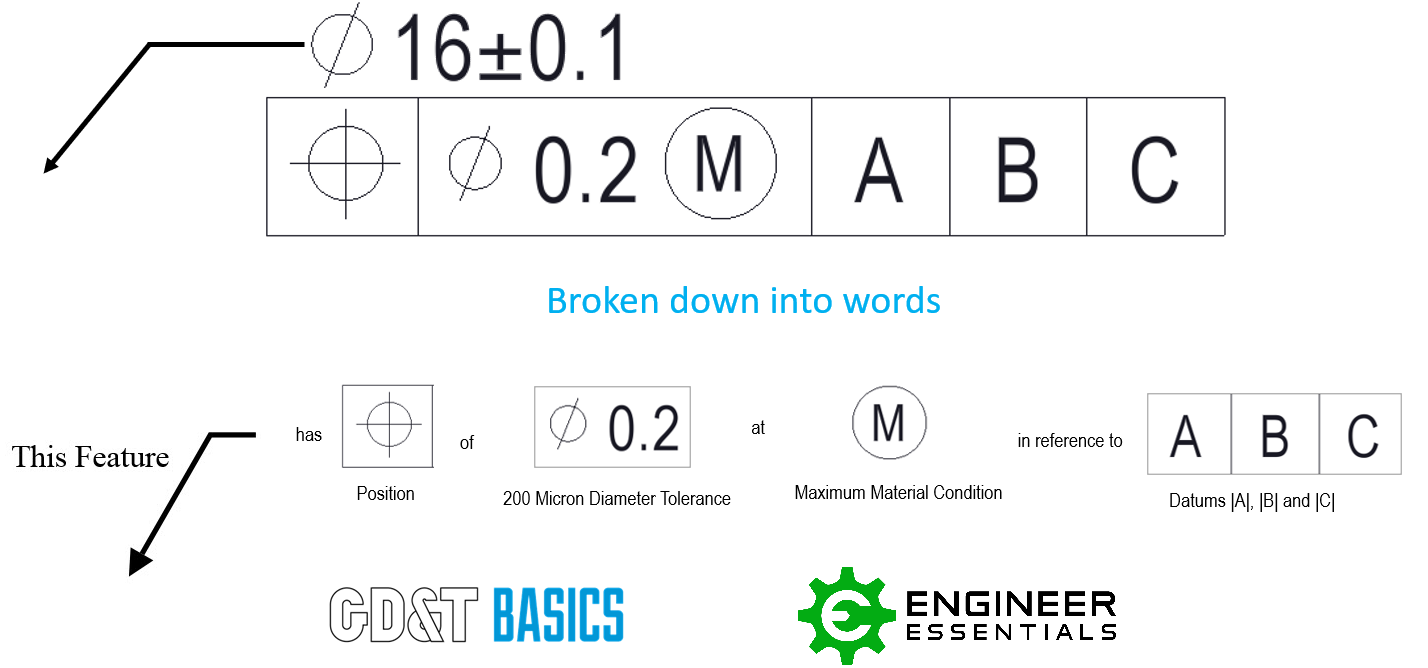
Be sure to check out our individual pages for each GD&T symbol for examples and specific uses of the feature control frame.
Placement of Feature Control Frame
The feature control frame can be placed on feature of size and surfaces. How the feature control frame is placed on the drawing will determine if the geometric control is on a feature of size (FOS) or a surface.
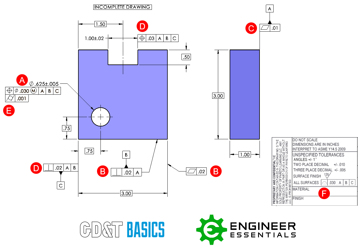
A. Feature Control Frame is located directly underneath or next to note/dimension of a feature. This is controlling a feature of size.
B. Feature Control Frame is attached to feature (or extension line relating to the feature) using leader arrow. Both instances shown here are controlling just the surface.
C. Feature Control Frame is attached directly to extension line of feature. This is controlling the surface associated with the leader line.
D. Feature Control Frame is attached directly to dimension extension line of feature. Take extra care to note that if the feature control frame is directly in line with the dimension, it is controlling that feature of size. However, if it is NOT directly in line with the dimension then it is controlling just the surface associated with that extension line.
E. Feature Control Frame is attached to an existing frame; this is generally used for refinement.
F. Feature Control Frame is placed in a note, chart, or tolerance block
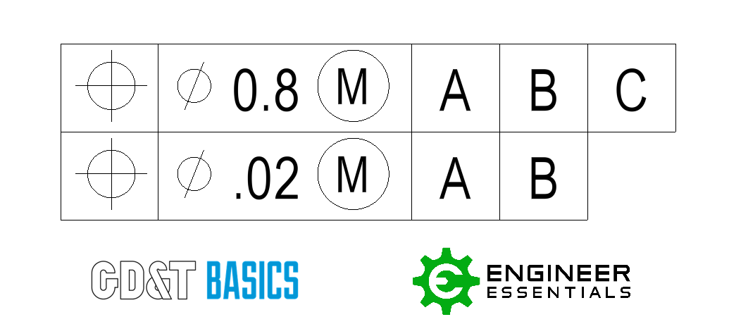
Composite Feature Control Frame
A Composite Feature Control Frame (FCF) contains two tolerance zone frameworks. It is shown to be a composite tolerance because there is one geometric symbol that spans across the two frameworks. Unlike MSS, for the Composite Feature Control Frame the top and bottom operate together. The bottom frame is considered a refinement of the top frame. For more explanation on how a Composite Feature Control Frame is interpreted please refer to our article “Composite Position vs Multiple Single Segment Tolerances”
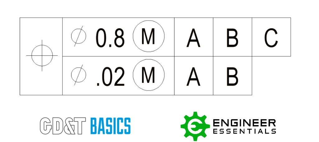
Multiple Single Segment Feature Control Frame
Multiple Single Segment (MSS) Feature Control Frames (FCF) contain two tolerance zone frameworks. However, the two frames are completely independent of each other. Multiple Single Segment Feature Control Frames will only utilize the position symbol or the profile symbol. For more explanation on how a Multiple Single Segment Feature Control Frame is interpreted please refer to our article “Composite Position vs Multiple Single Segment Tolerances”
Be The Go-To Engineer at Your Company
Learn GD&T at your own pace and apply it with confidence in the real world.
Get GD&T TrainingAll Symbols


Hi Matt,
I’d just like a clarification on a query. I have a drawing where the FCF is as follows: [POS][DIA 0.75 M][XYZ][X1] (3). Am I right in assuming that the datum for this feature relates to X,Y,Z co-ordinates as opposed to another feature in the drawing as these co-ordinates are shown on all aspects of the drawing?
Thanks
Paul –
I’m not sure what you mean with your datum structure. Is it possible that you are working to the 2009 standard that permits you to customize your datums with what degrees of freedom are restricted. I’m going to use generic datums A, B and C. Depending on your part you can dictate which datums restrict specific degrees of freedom, even if they are able to control more than what you specify.
For example a planar datum, is able to control 3 degrees of freedom (1 translational and 2 rotatational). The three translation degrees of freedom are specified as x, y and z and the rotational DOF are defined as u, v and w and specify rotation about x, y and z respectively.
Take a look at section 4.22 and 4.23 of the 2009 to help further with my example: Imagine a simple cone. Calling out the cone as a datum restricts 5 degrees of freedom. As mentioned earlier, calling out a flat plane restricts 3 DOF. If you have a shaft attached to the back face of the cone with a hole perpendicular to the axis of revolution, you could specify your feature control frame as |pos|dia 0.2|A [x,y,u,v]|B [z]|. The application is pretty rare though.
If I haven’t answered your question please feel free to reply and try again. I hope this helps.
Cheers,
Matt
Hello can anyone help me with an example of how and where are 3 datum used for a single feature??
Bharatwaaj –
Sure, first I want you to draw a 3 view drawing of a flat rectangular shape with hole in the middle of it. The size of the rectangle and hole don’t matter. You wish to use positional tolerance to locate and control the hole. Your feature control frame would read something like |pos|dia .010| | | |. I left the primary, secondary and tertiary datums empty for now, but we will be filling them in.
You want to control the perpendicularity of the hole to the flat surface, it won’t do any good to have a hole at a crazy angle. So you label the broad flat face as datum A and place it in the primary datum slot of your FCF. This is saying that the diameter of your hole must lie entirely within a cylinder (tolerance zone) of .010 that is oriented perpendicular to datum A.
You also to control the precise location of the hole from the bottom, long face of the part so that it attaches to another bracket. Label the bottom long face as datum B and place it in the secondary datum slot of your FCF. You are now saying that the tolerance zone is located theoretically exactly from datum B. The dimension from datum B is considered basic and has a box around it. It has no tolerance.
Lastly, you also want to control the precise location of the hole from the left, short face of the part so it assembles properly. Label the left, short face as datum C and place it in the tertiary datum slot of your FCF. You are now saying that the tolerance zone is located theoretically exactly from datum C. The dimension from datum C is also basic and has a box around it.
Your FCF now looks like this: |pos|dia .010|A |B |C |
You should read this as follows: A hole of a certain size and tolerance, located with a positional tolerance zone of diameter .010, perfectly oriented relative to datum A and located relative to datums B and C.
I encourage you to read through our position section of GDandTBasics.com. I would also highly encourage to enroll in our basic course, it has been very well reviewed and you will come away with a much greater understanding of the concepts at play.
Hope this helps, cheers.
Matt
What is the best way to call out a maximum “concentricity” between the inside and outside of a hex shaped tube? Is a hex shaped “coaxality” symbol in the first field of the control frame acceptable? The outside and inside dimensions of the tube are equal in tolerance but the wall stock is a reference. I want to specify somehow that that the maximum difference between the thickest wall and the thinnest wall is 0.014”.
can you explain about stackup analysis ? kind of calculating the tolerances
Can some one explain the all around symbol.
Brian –
The all over symbol means that it applies over the entire exposed surface of the part. If your part is a cube, that means the control (usually profile) applies to all 6 surfaces. If your cube has a hole in the middle of it the control also applies to the hole.
The all around symbol applies in 360 degree ‘loop’ in the view that it is shown in. If your part is a cube, the view shown is normal to the front face and the control is applied to the top/bottom/left or right surface, the control applies to 4 surfaces: Top, bottom, left and right. Omitted in this instance are the front and back faces.
Think of it this way –
All around: Perimeter
All over: Every surface that would get wet if you dunked the part in water
Cheers,
Matt
What is units of paralellism and flatness, mm?
Hans –
You’ll need to look at the title block of the drawing, located in the lower right hand corner of the drawing. It will (or should) specify, among other things, what units are to be used for the drawing in question.
Specifically, the tolerance for flatness and paralellism are units of length. Normally, this is given in units of mm or inches, but could possibly be something else.
Hope this helps.
Cheers,
Matt
what is difference between A-B and A (primary), B(secondary0 in feature control frame
ABC –
They are two functionally different things. The use of A-B would be in a scenario such as having two opposed nominally parallel cylinders and you want the axis created by both to be a specific datum. Referring back to my example, having |A|B| wouldn’t have any meaning as the inclusion of diameter B isn’t restricting any additional degrees of freedom. The choice to use |A-B| is driven by the design where the axis of both diameters matter. Typically, using |A|B| is the desire to control specific relationships on the part and dictating how the part is to be set up for inspection.
Hope this helps,
Cheers,
Matt
How would you read a feature control frame when M(Max material condition) is also next to 2nd or 3rd reference datum?
John –
It simply means that the datum that has the circle M (M) symbol next to it is to be taken at either the Maximum Material Condition (MMC) for the 1994 standard or the Maximum Material Boundary for the 2009 standard.
For the 1994 standard it means that the datum in question must be a feature of size that has a size tolerance and indicates that the feature is to be taken at either the MMC limit or the virtual condition as applicable. No attention was paid to higher precedence datums
For the 2009 standard it means that the datum in question can either be a feature of size associated with a size tolerance or a flat surface if used to control orientation. The MMB can is either the MMC limit or adjusted to reflect datum hierarchy.
In general, when you see either MMC, MMB or LMC, LMB next to a datum think in terms of functional gaging. You are stating that you want the functional gage at a particular size during inspection. The neat thing about all of this is that it allows for movement of the part on the gage to bring otherwise out of spec features back into spec.
Obviously, things are more detailed than I can provide a response to in a forum. If you’ve got a specific question feel free to come back and ask. We’re happy to help.
Meanwhile, check out our GD&T Basics – Advanced Course for material that you may find interesting. We’ve got something for everybody at every skill level.
Cheers,
Matt
What happens if you don’t use diameter symbol along with tolerance 0.03 in GD&T?
Yagna –
You are not adequately describing the tolerance zone if you are applying the tolerance to a cylindrical FOS. When referring to a hole or a cylindrical boss most people will see the feature control frame and know that you should have a diameter symbol in front of the tolerance. But for example, straightness as applied to a pin, having (or not having) the diameter symbol makes a big difference. With the diameter symbol the straightness is applied to the derived median line (sort of like the axis) and Rule #1 may be overridden. Without the symbol, the control is referring to the surface and Rule #1 still applies. I hope this helps.
Cheers,
Matt
how can i mention the tolerance value of 0.03
how we can calculate
Kranthi –
I’m happy to help, tolerance can be calculated using any number of methods. However, a flatness tolerance of 0.03 is not the same thing as a positional tolerance of 0.03. To really help you any further I’ll need more information on your specific situation.
Matt
I’ve got a strange one. It is a straightness call out but it is a compound call out. The call out is on a large disc .25″ thick and 66″ across and has the callout like it on the thickness.
The top frame has a .500 value which I would take to mean straight with .500″.
The bottom frame has a .250/33 value which I’ve no idea what this means.
Has anyone seen this sort of thing?
Jeff –
Can you clarify? Is the straightness tolerance being applied to the diameter with the MMC symbol or just pointing directly to the surface of the part? What are the tolerances for the diameter and the thickness of the part. Regarding the lower frame, it’s indicating how much straightness error per unit length is considered acceptable. This is to limit abrupt changes in the surface of the part within a specified length. In your case it would appear to be .250″ of straightness error every 33 inches.
Get back to us with some more information and I believe we can help.
Cheers,
Matt
is it possible to provide the FCF for basic dimension..?
Vishwanath –
I’m not sure I understand your question. Can you clarify?
Not all feature control frames require the use of basic dimensions. The use of basic dimensions does require the use of geometric tolerances (and thus feature control frames). This is because all dimensions have to have a tolerance and basic dimensions are theoretically exact.
If I missed the point of your question let me know and I’ll try again.
Cheers,
Matt
a feature must have perfect form when?
a)it is at MMC
b)it is at LMC
c)form tolerances are not specified
d)the form tolerance is specified without an MMC modifier
Paul –
The Taylor principle (also known as Rule #1 and envelope principle), specifies that you must have perfect form at MMC. Rule #1 provides an automatic form control on surfaces which is why form controls require the tolerance be smaller than the size tolerance so as to be a refinement. There are some exceptions to this rule, but that’s generally the case.
I hope this helps.
Cheers,
Matt
Hi Admin,
Please let me now.
In the MSA Drawing, there are feature control frame.
Is it refer to the basic value(box)?
Kindly help me.
Hakim –
MSA drawing? I’m not sure what you are referring to. Can you elaborate?
Cheers and Happy New Year,
Matt
How do you choose the tolerance value and from where do you get it? Is it the IT grade?
The tolerance value specified is driven by functionality. It represents the minimum value required to make the part work function. For controls like flatness or angularity only you can determine what this value is. The only control that has a set calculation is for position. The fixed fastener formula: Tolerance is equal to the MMC hole size minus the fastener size all divided by 2. The floating fastener formula: Tolerance is equal to MMC hole size minus the fastener size. Hope this helps.
Thanks
CZ means Common Zone
All features must be within the common tolerance zone
You are absolutely correct. CZ stands for Common Zone and this term is only found in the ISO standard for GD&T. I have no experience with the ISO standard, but I’ll see if I can’t get a more detailed reply from one of our guys who is.
Please explain more about Placement of Datum and Feature Control Frame with images.
what means CZ in a feature control frame?
for instance: total profile of 0.3 CZ in reference to datums A B and C
thanks
Manuel –
Can you provide any more information? I’m not sure what you mean. Are you seeing this on our website somewhere or another drawing/website you found? Can you tell me in regards to what spec is being called out (ASME vs ISO)? Per the ASME spec there is no recognized symbol or modifier ‘CZ’. Is it possible that it’s a typo on the drawing, are the letters CZ enclosed in parentheses, hexagon or circle? I’m curious to find out what exactly it is that you are seeing and where you are seeing it.
Matt
CZ means common zone in drawings
Hello, How to read this dimensions shown below?
4X ø .072
.065
˅ ø .120 101(degree)
X
.110 99(degree)
4 holes with a diameter of .065- .072 with a countersink of 99-101 degree with a diameter of .110-.120
what will be the unit of “tolerance value”. You had written that your examples are in metric form. But what wil be the global unit for that.
Hello Jogi – The units can be either metric or inch – as long as the units are consistent you are fine. There is no requirement.
Please confirm that how to find out tolerance value as 0.03 mentioned in feature control frame?
Tolerances in the feature control frame are listed in the drawing as total tolerances meaning the entire tolerance zone is 0.03.
Please confirm what is diametric tolerance, as refered above in your example, is it ±30 micron or +15/-15 mircon.
All geometric symbols use a total tolerance by default. There are ways with profile to provide a unilateral tolerance, but when you see a tolerance for the symbols, it means the total tolerance range that the features axis, point plane or surface can fall into. In your question it would be ±0.015. – but remember – many of the symbols do not control size, so there is no nominal dimension that the ±0.015 is based off of, the tolerance simply allows the feature to “vary” by up to 0.030. The size tolerances are a separate issue entirely for most default symbols
+_30