
Special Note:
Parallelism actually has two different functions in Geometric Dimensioning and Tolerancing depending on which reference feature is called out. The normal form or Surface Parallelism is a tolerance that controls parallelism between two surfaces or features. The surface form is controlled similarly to flatness with two parallel planes acting as its tolerance zone. Axis Parallelism is a tolerance that controls how parallel a specific parts central axis needs to be to a datum plane or axis. The axis form is controlled by a cylinder around a theoretical perfectly parallel axis. Parallelism is most commonly called out as surface parallelism. However, be sure to pay attention if it is referencing a central axis because it is different! We will only discuss surface parallelism on this page but be sure to check out our page on Perpendicularity to see how an axis is controlled with GD&T.
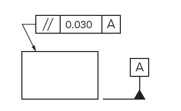
GD&T Symbol: 
Relative to Datum: Yes
MMC or LMC applicable: Yes
GD&T Drawing Callout:
Description:
Parallelism is a fairly common symbol that describes a parallel orientation of one referenced feature to a datum surface or line. It can reference a 2D line referenced to another element, but more commonly it relates the orientation of one surface plane parallel to another datum plane in a 3-Dimensional tolerance zone. The tolerance indirectly controls the 0° angle between the parts by controlling where the surface can lie based on the datum. See the tolerance zone below for more details.
Note: Parallelism does not control the angle of the referenced feature, but only creates an envelope in which the feature must lie.
It is important to determine what the reference feature is (surface or axis) and then what is acting as the datum (surface or axis) to determine how the parallelism is to be controlled.
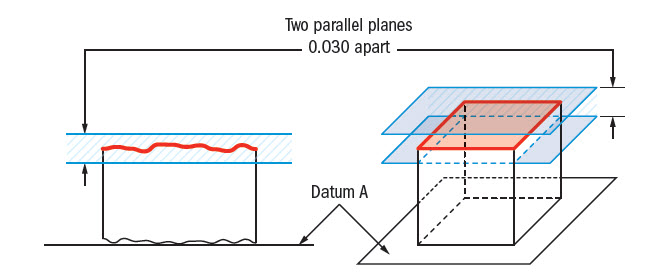
GD&T Tolerance Zone:
Two parallel planes or lines which are oriented parallel to the datum feature or surface. All points that are on the referenced feature must in the tolerance zone.
Remember: Parallelism does not directly control the angle of the referenced surface; it controls the envelope (like flatness) where the surface needs to be. The goal is to ensure all points are within a specified tolerance distance away from their corresponding datum points.
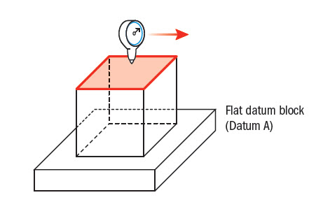
Gauging / Measurement:
Parallelism is quite simple to measure. Like flatness, a gauge is run across the reference surface or feature. However, unlike flatness, the part is constrained against a granite block or flat plane that acts as the datum surface where it is measured.
Relation to Other GD&T Symbols:
Surface Parallelism
Parallelism is a specific form of angularity only at 0°/180° instead of a called out angle. All the profiles of orientation and are used in the exact same way. All of the orientation symbols (angularity, perpendicularity, and parallelism) all call out the particular feature envelope referenced to a datum.
The Parallel Symbol is also closely related to flatness when referenced/measured surface is flat. When you call out parallelism, flatness is implied (you are measuring a surface variation between two parallel planes = flatness) However the biggest difference is parallelism is measured with respect to a datum, ensuring both the datum and reference feature are always parallel.
When Used:
Whenever two surfaces or features need to work in sync with each other and constant distance must be maintained, parallelism is effective. Whenever you have a part that must always fit nicely between two planes that need to reference each other, it comes in handy. Even though surface parallelism seems to ensure that a flat surface is mating with another flat surface, it can also be applied to two sides of a hole or cylinder to avoid a taper. Any part with two critical flat surfaces such as gears would call out parallelism.
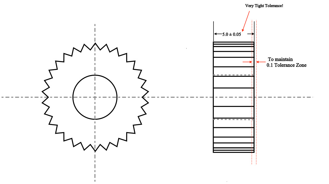
Parallelism Example:
A gear has to maintain constant axial load on both faces. To ensure even contact one side of the gear is held parallel to the other side. To do this without parallelism, the gear width would have to be tightly controlled, which could be very difficult to do.
Ensuring even surfaces without GD&T
With parallelism, you can open up the dimension of the gear and control the faces without rejecting good gears.
Controlling two faces with GD&T parallelism callout.
Final Notes:
Combination of Orientation and Form:
Parallelism is very common in its surface form. When dealing with any flat surfaces, flatness may be called out, but parallelism is usually more critical since the relation of surfaces in an assembly is more important.
Max Material Condition with Axis:
Straightness, Axis Angularity, Axis Parallelism, and Axis Perpendicularity can all be called out and controlled with a gauge in maximum material condition. However only perpendicularity and straightness are used commonly. Please see our page on Maximum Material Condition for more information.
Be The Go-To Engineer at Your Company
Learn GD&T at your own pace and apply it with confidence in the real world.
Get GD&T TrainingAll Symbols


Hello,
Its a bad practice to use three datum’s in a single drawing callout for a parallelism simbol?
I have a drawing with a parallelism callout referencing two datums. One is a plane and the other is a hole. Is that right? Can you even have two datums for parallelism?
Joe –
I can think of examples where you could, but I’m struggling to think of scenarios where you would. The other two orientation controls, yes, you absolutely can use multiple datums. I can’t find anything in the standard on it. Can you tell me more? Is the feature you’re trying to control with parallelism control a flat surface or a feature of size?
Matt
how much parallelism variation can there be when the SIZE dimension between two surfaces is +/- .015″?
wouldn’t it be .030″, the amount of variation?
James –
You are correct. This follows from Rule #1 which states that you must have perfect form at MMC. The follow on to that is that as your part departs from MMC towards LMC you are permitted form error equal to the amount of departure. In your case this would be .030. Hope this helps.
Keep coming back and contributing to the community knowledge base.
Cheers,
Matt
I just came upon a print that uses a parallelism specification with an LMC modifier on the datum. That seems like a mistake, correct?
Dave –
It depends. If the parallelism callout is in reference to a planar surface then neither MMC or LMC are permitted. If the feature control frame is in reference to a feature of size, a hole for example, then MMC and LMC are permitted tolerance modifiers. In either case, planar surface or feature of size, the MMB and LMB callouts for datums are always permitted. I hope this helps clarify your situation.
Cheers,
Matt
Hi Matt Derr,
I saw there are some drawing state parallelism without datum:
(1) normally is: |//| 0.05 | A |
(2) but some are: |//| 0.05 |
For (1), just as your example, place the part on the granite as datum A, and measure through sliding the opposite surface by height gauge.
For (2), due to no datum mentioned, is it we can use caliper/ micrometer to measure the thickness, and, take the max – min = to get the parallelism?
SFC –
I’m not sure where you are seeing parallelism callouts without reference to a datum. Datums are ALWAYS required when calling out ANY of the orientation controls (parallelism, angularity, perpendicularity). This even applies when using an orientation control in a composite feature control frame to refine another control like position. Under no circumstance is an orientation control to be used without a datum.
I hope this helps clarify things a bit.
Cheers,
Matt
Hi guys,
I think that the second situation is possible when we have direct references of one surface to the other. (|//| 0.05 | must have the arrows directly on both of the surfaces)
Could you tell me what the number after a forward slash means? E.g.
// | 0.015/100 | A.
Is it the envelope of the tol. zone?
Regards
Matt
usually, that means per unit length – I have never seen it used with parallelism though – it is more common with flatness/straightness
The print has a Basic Dimension of 370.5 with a parallelism feature of 1.0 in reference to (2) flat plates connected by a tube. Is it safe to say a part measuring between 370.5-371.5 is in spec and a part measuring at 369.5-370.5 is also in spec?
Amy –
Without seeing more I would hesitate to make that statement. Parallelism, like all orientation controls, does not dictate the location of a feature. The tolerance zone is represented by two parallel planes spaced 1.0 apart and oriented parallel to your datum surface. The location of the tolerance zone exists wherever the surface exists. Your parallelism tolerance (from the feature control frame) should be a refinement of other controls (limits of size, position, runout, profile). The most common example is from limits of size, as just having a size tolerance of X +/-0.X includes an inherrent parallelism tolerance.
I hope this clears up some confusion on your part. If you have additional questions please feel free to come back any time and ask questions. I’d encourage you to take a look at out GD&T Basics course! We have a lot of information to share and we feel that our course pricing is well worth it.
Cheers,
Matt
is it ok to have .000 as a parallelism requirement?
Arthur –
Interesting question, but no. Think about the tolerance zone. The tolerance zone for parallelism is typically two parallel planes. The space between them is defined by the value in the feature control frame. So you would have no distance between planes, i.e. a single plane. There is just simply no way for all elements of any surface to perfectly exist in a single plane.
Hope this clears things up for you.
Cheers,
Matt
Hi I have a question about bended tube (2 bends with 90 deg.)
The datum A is called out on the inside surface of a tube. The opposite side of the tube has an installed machining part (reducer) with a thread ending to further install other parts to the tube assembly. The parallelism 0.2 is called out on the thread, opposite of datum A. Due to the surface of the thread (picks and valley), the picks could be parallel but valleys not.
1.) What would be your approach to inspect the part?
Due to the inside of the tube is defined as datum A i can’t just put the part on the surface plate and measure the opposite side.
2.) Is this call out correct?
1) which is the correct method for measuring parallelism?
1) micrometer
2) height gauge (with help of probe taking some points on their surface)
3)dial indicator method
2)without surface table how can I measure parallelism?
Ganesh –
There really isn’t one single method for inspecting parallelism. I’m guessing, however, that since your asking you don’t have a CMM handy. The simplest method would be to place the datum in contact with your inspection surface. Then with a dial gage on a stand measure the maximum variation between the high and the low points of your controlled surface. The difference between the max and min gage reading is the parallelism error of the surface in question.
Thanks for the question and contributing to the community knowledge base. I hope this helps.
Cheers,
Matt
Hi,
This is Magesh, i have a? regarding Flatness & Parallelism in sheet metal press part.
Parallelism spec is max 0.08mm, which it having the thickness is 3.85+/-0.05mm.
Since it is a safety part. I want to control parallelism with in the spec.
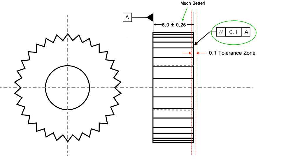
Hi, I have a question about the gear example, where you have added the GD&T improvement…
We have the width tolerance of 5.0 ± 0.25mm with a parallelism of 0.1mm.
Let’s say I measure a part with an average width of 5.249mm, which also passes the 0.1 parallelism.
If there are “high spots” on the surface where 5.25mm is breached – is that ok?
To put it another way, does the 5.0 ± 0.25mm apply only to the average value for the face? With the parallelism being an entirely separate constraint?
Hope that makes sense. I’m getting drawings through with ±0.25mm (hence 0.5mm range) on a dimension with 0.5mm parallelism. This doesn’t look like good practice but it could potentially give me a bit more room to play with.
No – High spots are not ok – the part must pass within two flat planes of 5.25 to pass inspection. The parallelism cannot cause the part to ever exceed its size tolerance. This is due to the envelope principle or rule#1 in GD&T. We will be releasing a page on this soon, but ultimately your max size tolerance for an external feature, like the gear would be an absolute boundary that no point could cross.
Hi, I’m trying to figure out how the tolerance opens up from 0.05 to 0.25 on the gear example. Maybe I missed something. Could you please advise? Thanks!!!
If the goal is to ensure that the one surface is parallel to the other, you would normally need a tighter size tolerance if you were not using GD&T. However, with the parallelism callout, you can now have the size tolerance set at whatever you want since you are specifying that the one surface is now parallel within 0.1. The shape of your part can now be independent, of the size, allowing you to control the size as loose as functionally possible.
Hi, is correct include into the Datum a Tolerance of Flatness and opposite add a tolerance less than Flantess Tolernce?
Thanks for you advise..
What is be the ratio between parallelism and flatness?
Motiram –
There is no ratio between parallelism and flatness. I’m not sure I fully understand your question so I’ll do my best to explain the differences between the two.
For my explanation I’m assuming that we are tolerancing flat planes, for example: a rectangular brick
Similarities: Both use a tolerance zone defined by two theoretically exact parallel flat planes that are spaced apart a distance equal to the value specified in the tolerance block of the feature control frame.
Differences: Flatness is only inspected against itself, it is not oriented in any way. As long as the entire surface fits between the flatness tolerance zone your part is considered to be ‘in-spec’. The flatness tolerance zone is allowed to shift, tilt or translate in any manner. Parallelism is referenced against a datum. Here the tolerance zone is theoretically oriented exactly to a reference datum. Again, as long as the surface fits entirely within this zone the part is good. Here, the tolerance zone is only allowed to shift or translate, it may NOT tilt in any manner.
I hope this helps clarify things a bit.
we have surface (A) with 0.02 flatness,another surface must be have 0.02 parallelism with surface (A)
My qst is:
Parallelism given spec is OK ? really can effect of flatness on parallelism?
Yes parallelism controls your flatness to the same amount, while also controlling orientation.
I’ve seen a method which draws Surface finish symbol on the tolerance frame. Is this correct?
Sandeep –
There is no provision in ASME Y14.5 that describes the use of a surface finish in conjunction with a feature control frame. Typically, surface finishes are part of the title block and any exceptions to this could be taken care of using a flag or ‘delta’ note that is called out in the field of a drawing. As long as the intent of the callout is clear it may work, but unless you’ve been dealing with the same set of vendors for a long period of time and their used to your methodology expect a call regarding the meaning.
I hope this helps.
Cheers,
Matt
Hi. I don’t know which geometrical tolerance to use in my case. I fix a screw with square head against a thick square metal plate. The plate is bigger. I need the side faces of the screw head to be parallel to the side faces of the metal plate, so that it looks like both square shapes are aligned (So it looks like an small square inside a bigger one, but aligned).
I was planning to put a the datum on one side of the metal plate, and put the parallelism tolerance on the corresponding face of the screw. Is this correct? I want to keep less than 2° angle between both faces, but I understand that parallelism does not control the angles, so I don’t know to properly specify the geometric tolerance.
Thanks!
Charly –
You methodology would certainly work as far as calling out a control on the edge of the bolt. However, I wonder how well this would work practically. It becomes an issue of where the threads start relative to the flat faces. My point being that when you tighten the bolt you may find that the edges will not line up. Then, to either tighten or loosen the bolt to meet the requirement may not produce sufficient clamping force to keep the assembly together or you may strip threads.
Now, on to your next comment regarding angles and the parallelism requirement. You are absolutely correct in that the orientation controls (perpendicularity, parallelism and angularity) do not provide a tolerance in terms of an angle. They specify a width between two parallel planes that are oriented relative to a datum. Only within this oriented width is the controlled surface allowed to vary and still be within specification. As far as how to convert your angular requirement in terms of degrees into a width for a tolerance? Some simple geometry does the trick.
In your case take the length of bolt edge (I call it l) and multiple by the sine of 2 degrees. This will tell you the maximum width permissible for your parallelism control.
Hope this helps. Cheers.
Matt
Matt,
Thanks Matt, that was quite helpful.
The conversation here began with a supplier engineer asking if it was allowable to have a parallelism on the top surface with the same allowance as the flatness on the datum surface, with the thinking being that one might “eat into” the other – for instance, if one side were cupped, and that happened to be the A datum, it may have a rather poor flatness, but when you flip it and work with a simulated A datum, and the surface is sitting on the outer high spots, the top surface (we’ll assume it’s NOT concave or convex on this side) may appear to be quite parallel when in some respects it really isn’t. Meaning both flatness and parallelism may squeak by because of “fixturing” methods.
But again I guess in theory this is correct, as it’s assumed that the part will indeed be sitting on the A datum’s highest points, so as long as it meets that “thickness” or height control throughout, all is acceptable (and if the thickness tolerance were to be opened up, the parallelism would simply be insuring that whatever the thickness, it remains pretty uniform throughout. So I guess that covers my questions pretty well.
Thanks again,
Bob
Hi, I’ve got a simple(?) question on a simple part. We’ve got a small, steel rectangular block. It has a thickness of 3mm +/- .02, a flatness callout on one side (datum A) of .05mm, and a parallelism callout on the opposing face of .05mm. Aside from the obvious, I think, issue of allowing the parallelism to vary more than the allowed thickness, do these matching tolerances for flatness and opposing side parallelism make sense? Secondary question – suppose these parts were symmetrical, having no true “up” or “down” side…would these callouts still make sense if they needed to work with either face up/down? Third question, partly covered in your answers above, if a flatness callout were also added to the opposing side, would be still make sense to use .05mm for this as well? Or would the parallelism or flatness need to be “tightened” in order to serve any purpose?
Thanks!
Bob –
1. You are correct. Parallelism of a surface needs to be a refinement of the size tolerance. In effect, there is no additional parallelism requirement being levied against the surface opposite datum A in your example. This is due to the effects of rule #1 (perfect form at MMC). If the block was manufactured at 3.02 there could be no form error on the part. As the block departs MMC towards 2.98 (LMC) the amount of form error allowed is equal to the amount of departure. Thus, the maximum parallelism error that could be found in the part that is inherent from the size tolerance alone is 0.04. I realize that parallelism isn’t a true form control (it’s orientation) but parallelism is essentially an oriented flatness control.
2. As far as the part being symmetric and whether it would work in either case, up/down whatever. That is really a question that I can’t answer for you. The engineer/designer has to take into consideration the effects of having a slanted surface and what implications there would be as a result of assembling in a different manner (if the design allows for it). The quick/simple example is this: If you make a wedge doorstop from a 2 x 4 will it work with the hypotenuse up or in contact with the floor? The answer is yes, but there is a difference.
3. Be aware with flatness that no orientation is required, you are holding the surface flat to itself. Your tolerance zone is just two parallel planes spaced some distance apart. You can orient and move the planes in any manner such that the entirety of the controlled surface fits within the zone. Also, as I mentioned earlier, parallelism has an indirect flatness control in it as the tolerance zone for parallelism is two oriented planes spaced some distance apart. With parallelism you have to orient the planes relative to your datum but you are still allowed to move the planes up and down such that the entirety of your controlled surface fits within the zone. So, if you wanted to add a flatness control in addition to the existing parallelism control it would have to be a refinement of the parallelism control.
I think I’ve answered your questions, but if you have more or need further clarification we are happy to help. Let us know what we can do.
Cheers,
Matt
hi
we have a 10mm plate, datum A with 0.1 flatness, another surface must be parallel 0.02 reference to Datum A
my question is:
How do we measure the flatness with method
1. Height gauge
2.CMM
Hope you can enlightened me
Sukhairi –
The use of a dial indicator to determine parallelism (you say flatness, but I think you mean parallelism) is pretty straightforward. Using an articulated tool stand position the dial indicator over the surface. Place the tip of the probe such that it is in contact with the controlled surface and reset the dial to 0. Without changing the height of the indicator, run the probe over the surface of the part. The difference between the maximum and minimum dial indicator reading will tell you the parallelism error of the surface.
The use of a CMM is really dependent on which specific software you are using and what tools you have on hand. I can’t really help all that much there other than to say you’ll need to run the probe over the datum feature simulator surface (usually a precision granite inspection table) and then over the toleranced surfaced. The computer will spit out a 3D plot that interpolates your probe points as a map and tell you if the part is in spec.
I hope this helps.
Cheers,
Matt
hi sukhairi
from my view if you use CMM to measure a 10mm plate flatness it will be a cost effective and a non economic means, so it is better to use a height gauge by probe run method.
Using a height gage with a probe is certainly a tried and true method. If you happen to have a CMM available in your shop or as part of your company’s quality/inspection department there really is no cost or time penalty associated with it. It all depends on what inspection tooling you have on hand.
Matt
hi
we have surface (A) with 0.02 flatness,another surface must be have 0.02 parallelism with surface (A)
my question is:
when we want measure the parallelism we should use a flat surface(like granite) as reference or a surface parallel with surface (A)?
if you want i can send the draft for you
tnx
Mostafa –
You would place datum A in contact with the granite surface. The surface is then acting as your datum feature simulator and is then what you would measure from with regard to your parallelism requirement. Using a portable dial indicator with a stable stand (also in contact with the granite surface) you would run the indicator over the surface with the // requirement to find the maximum variation between peaks and valleys. The difference between the peaks and valley readings is then the parallelism error of the measured surface.
I hope this helps.
Cheers,
Matt
thank you for your description
can with use magnet with ideal flatness instead of granite because the thickness of surface is 1 mm so with out magnet force the datum surface doesn’t contact with granite completely
tnx
Mostafa –
If I understand you correctly you want to essentially restrain the part using a magnet. There is nothing wrong with this as long as it states on the face of the drawing that measurements are to be made in the restrained condition using “insert method here”. Otherwise the machine shop could be producing parts that meet the requirement in the free condition that warp when restrained or vice versa.
With bent sheet metal parts we often have a note at the bottom that states to measure only after inserting 8 #10-32 screws with a torque of 45 in-lbs. What you are doing is essentially measuring the part in the condition in which it will ultimately be used in.
I hope this helps with your project. It’s good to know that we are helping engineering firms and students globally.
Cheers,
Matt
How can i calculate parallelism using two planes (=, top & bottom), can i calculate using flatness ?
Parallelism and flatness are essentially the same requirement. The difference being that parallelism (along with the other orientation controls) are constrained relative to a datum. Flatness is without a datum and is held only relative to itself.
An example of measuring a parallelism requirement would have a dial indicator resting on the same surface that the referenced datum is resting on. The dial indicator tip contacts the controlled surface and the difference between the maximum and minimum indicator reading is equal to the parallelism error of the part surface.
Hope this helps,
Matt
Hey. Im getting this tolerance on a drawing saying —> |parallelism|Ø2(M)|A|
Is this correct? never seen a combination of this before.
Please helg explain if possible.
Greetings
Chriss
Chris –
Absolutely, first I should hope that your control is applying to a cylindrical feature of size as that is the only case in which you could use the diameter symbol in conjunction with the MMC symbol. Next, I hope that datum A for your part is either another cylindrical feature, like a hole or a pin (preferably) or a flat surface. What this control is telling you is that your cylindrical feature with this control is basically located relative to your datum and must be parallel within a diametrical tolerance zone of 2 at MMC. As your hole size departs from MMC towards LMC you are allowed a ‘bonus’ tolerance identical to that which you would have gotten with a positional callout at MMC. If you have ASME Y14.5 – 2009, I would recommend you look at Figure 6-10 which should represent your case pretty closely.
I hope this helps, if not let us know and we’ll do what we can to help you out.
Cheers,
Matt
How we decide the final parallelism when flatness is also observed out of specification?
Lets parallelism observed 0.2 and flatness observed 0.1 .
Is finally parallism = parallesim-flatness
Please help
Hi – I’m not positive I fully understand your question but here goes. Flatness is independent of a datum whereas parallelism requires the use of a datum. Bear in mind that in a situation where you are using both parallelism and flatness, the flatness would be a refining control. This is because by using a parallelism control you get an inherent flatness control with it. Flatness is only keeping the desired surface controlled relative to itself, i.e. no orientation.
In your example the parallelism zone is two planes, separated by 0.2, oriented parallel to a specified datum. The refinement has the surface controlled by a zone defined by two planes separated by 0.1 (not oriented or located at all). As long as the surfaces fits within both zones simultaneously the part is good. Any portion of the refined tolerance zone that breaks the barrier of the larger tolerance zone are unusable. Another way of thinking about this is to draw two lines parallel to your datum 0.2 apart. Now, two additional lines can be drawn within this area spaced 0.1 apart. The flatness control may shift up and down and rotate within the larger 0.2 zone.
Does this help? Let me know otherwise.
Cheers,
Matt
How does parallelism affect on concentricity of holes? (e.g. // of plane is 0.2, what will be max. limit of concentricity of holes on that plane?)
parallelism of an axis is indirectly controlled by concentricity – but not the other way around. This is because parallelism does not affect the location of the axes in space, only their orientation.
in one datum plane two same dimension spot face surface.how to check parallism
dear sir
plaese help in slection of tolerance for gd&t i.e. who much tolerance we give to a particular gd&t symbol
The short answer for how much tolerance is always the same – You should give the maximum amount of tolerance, that allows your part to perfectly function. Every situation is different and typically is derived from historical applications that are similar.
thank you