
Symbol: CR
Definition:
The Controlled Radius is a variation of Radius. It dimensions the size of a circular feature using the radius length, but it also gives an additional requirement – that the surface of the contour must be a “fair” curve. This means that the surface must be continuous, without reversals.
Application:
When a Controlled Radius is required, the symbol “CR” is placed before the size dimension, as shown below in Figure 1.
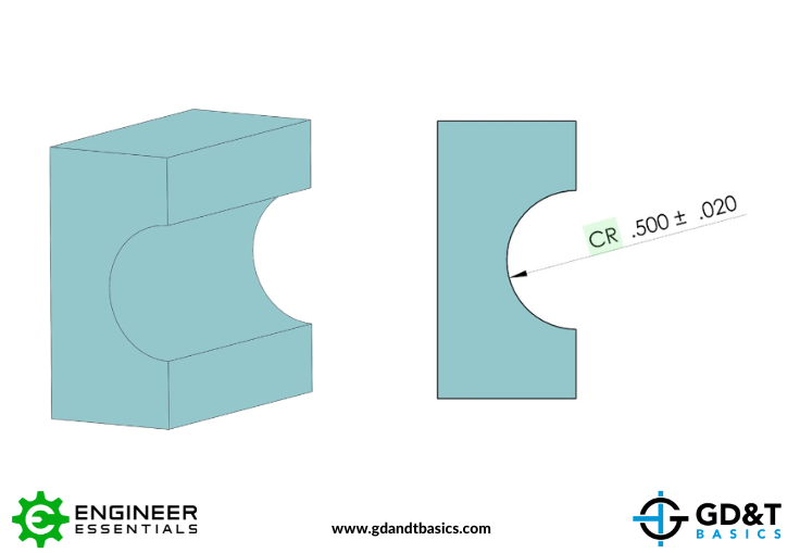
Figure 1: Circular Feature with Controlled Radius Dimension
The difference between a Radius and a Controlled Radius is in the contour of the machined feature. While points along the “Radius” dimensioned surface must only fall within the tolerance zone, points along a “Controlled Radius” surface must fall within the tolerance zone AND be a continuous arc, as shown in Figure 2.
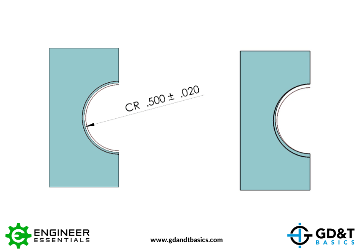
Figure 2: Machined “Controlled Radius” within Tolerance Zone
The requirement for a Controlled Radius may be common on critical bore surfaces or bearing surfaces. When machining, a Controlled Radius is achieved by slowing down the machine’s feed rate to prevent reversals.
The one-page GD&T reference that you will use every day
A visual breakdown of every core GD&T symbol and what it controls, all on one page. Bookmark it. Print it. Actually use it.
Download the ChartAll Symbols


