
GD&T Symbol: 
Relative to Datum: Yes
MMC or LMC applicable: Yes (Uncommon)
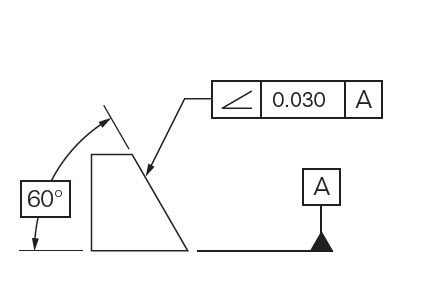
Drawing Callout:
Description:
Angularity is the symbol that describes the specific orientation of one feature to another at a referenced angle. It can reference a 2D line referenced to another 2D element, but more commonly it relates the orientation of one surface plane relative to another datum plane in a 3-Dimensional tolerance zone. The tolerance does not directly control the angle variation and should not be confused with an angular dimension tolerance such as ± 5°. In fact, the angle, for now, becomes a Basic Dimension, since it is controlled by your geometric tolerance. The tolerance indirectly controls the angle by controlling where the surface can lie based on the datum. See the tolerance zone below for more details.
Maximum material condition or axis control can also be called out for angularity although the use in design and fabrication is very uncommon since gauging a hole or pin at an angle is difficult. When angularity is called out on an axis, the tolerance zone now becomes a cylinder around the referenced axis at an angle to the datum. The page on Perpendicularity goes into this type of reference in further detail since it is more common with perpendicularity.
GD&T Tolerance Zone:
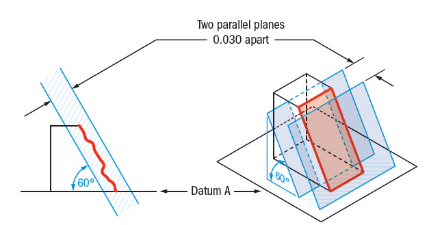
Two parallel planes or lines which are oriented at the specified angle in relation to a datum. All points on the referenced surface must fall into this tolerance zone.
Angularity does not directly control the angle of the referenced surface; it controls the envelope (like flatness) that the entire surface can lie.
Gauging / Measurement:
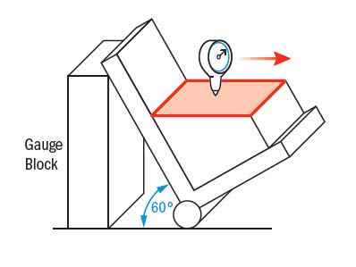
Angularity is measured by constraining a part, usually with a sine bar, tilted to the reference angle, so that the reference surface is now parallel to the granite slab. By setting the part at an angle the flatness can now be measured across the now horizontal reference surface. The entire variation must not fall outside the tolerance zone.
Relation to Other GD&T Symbols:
Perpendicularity and Parallelism are actually refined forms of Angularity. Perpendicularity describes angularity at 90° and parallelism describes it at 0°. All of these are profiles of orientation and are used in the exact same way. They also can be used with control of an axis under maximum material condition, although perpendicularity is usually the only one you will ever see with this callout.
Orientation Geometric Dimensioning and Tolerancing Symbols are also closely related to flatness when the surfaces are is flat planes. When you call out any of the orientation symbols, flatness is implied (you are measuring a surface variation between two parallel planes = Flatness) However the biggest difference is that orientation callouts are measured with respect to a datum, where flatness is not.
When Used:
Angularity helps control any feature that is at an angle to another datum surface. Anytime you have a critical feature which mates with other parts at an angle, angularity can be used to help control the angle and flatness of the mating surfaces. Many stamped parts that have bent features use angularity to ensure that the 3D surface formed by the stamping operation that is formed always is controlled and encased in a tolerance zone.
Example:
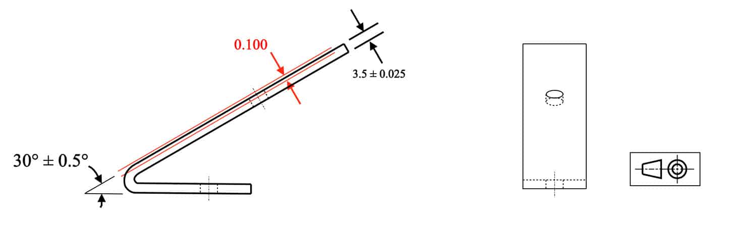
If you have a stamped part that had to hook into another part at an angle of 30 degrees, you would want to call out angularity on the “bent” feature to ensure that it is always at its proper orientation. If you did not use angularity you would have to both tighten the angle tolerance of the part and the thickness tolerance of the referenced surface.
Angularity example 1: Tightening the angle and/or the thickness are required if angularity is not called out.
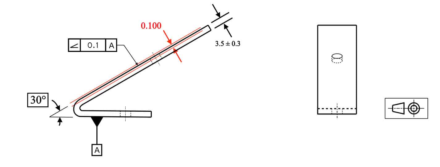
Angularity example 2: A simple call to angularity now ensures that the stamped surface now has both proper angle and flatness. The angle must be a basic dimension but now allows your part thickness to open up more. (Note this drawing is unconstrained and would need additional size dimensions to be accurate.)
Remember – You are not controlling the angle with angularity – you are controlling the surface to fall within the specified dimensional tolerance in millimeters!
Final Notes to Remember:
Datum Relationship:
Since all of the orientation symbols (Angularity, Perpendicularity, and Parallelism) are referenced to a datum – essentially the tolerance is not measuring a specific surface or feature on its own. You are measuring the relationship of one feature or surface with respect to another feature. If one feature is out – both surfaces could be incorrect.
Maximum Material Condition:
Maximum material condition can also be used in a similar method of perpendicularity. Although MMC is usually for pins or holes which need to be perpendicular to a reference surface, so it is not commonly used on angularity. See Perpendicularity for more details about Gauging and Calling out MMC on an orientation symbol.
Dimensional Angularity:
As stated before: 2-Dimensional references can also be used with angularity to ensure that an angle is met around a round or complex feature. If you wanted to specify the angle of a cone, for example, the angularity would apply to each line element along that cone referenced to the bottom of the cone.
Be The Go-To Engineer at Your Company
Learn GD&T at your own pace and apply it with confidence in the real world.
Get GD&T TrainingAll Symbols


I have an angle dimension that is listed as a basic dimension, the only control frame is for positional tolerance, how do i calculate or interrupt this?
Loren –
I’m guessing that your drawing is trying to locate the center of a hole relative to your datum structure. Do you have any other basic dimensions on your drawing? Look at your drawing and see where your datums all intersect. Make a mark in red pen at that point. Your hole must be oriented and located relative to that point through a combination of basic dimensions and angles. Keep in mind that the term basic means theoretically exact. I say point, but in reality the datums are almost certainly intersecting in a single line.
I hope this clears things up for you. If not, please come back and ask more questions.
Cheers,
Matt
Objective of angularity inspection ?
Barath –
I’m talking about surfaces for this example. Angularity is essentially an oriented flatness control. The tolerance zone is two parallel planes oriented by some basic angle relative to an identified datum plane. The entirety of the controlled surface must lie within the tolerance zone to be considered in specification.
I hope this helps clarify things for you. Come back any time with additional questions.
Cheers,
Matt
How can I calculate the angle between two points with tolerances?
Sample; The tolerance of point A is +/- 1.5 and the tolerance of point B is +/- 1.1. According to these tolerances, what is the angular value of point B according to the point if I do not draw a line between two points?
IVE BEEN HEARING THIS LATELY, AND HAVE NEVER HEARD IT BEFORE. ” FOR EVERY 1° ANGLE DIFFERNCE, (OFF KILTER) THEIR IS A .030 DISCREPENCY IN A HOLE DIMENSION CALLOUT.
IS THEIR A FORMULA THAT STATES THIS?
ILL ASSUME THIS MIGHT BE TRUE FOR A GREATER DISTANCE BUT TRYING TO VERIFY A TRUE POSITION TOLERANCE OF A HOLE IN A FORMED PART. THE ANGLE SEEMS TO ONLY AFFECT ONE DATUM, THUS CONFUSING THE VALIDITY OF THIS STATEMENT? ANY HELP, THANK YOU!
Jamie –
That is somewhat odd, I’ve never heard of that rule of thumb before. I have a hard time taking it at face value as it’s totally dependent on the thickness of the material you are dealing with. The axis of your hole moves a distance equal to [(h/2) * tan (alpha)] where h is the thickness of the material and alpha is the tilt angle.
I hope this helps.
Cheers,
Matt
Matt, I have an older drawing that has a dimension of 1 degree-3 minutes. The Feature Control Frame tolerance for angularity is +/- 2 degrees. Imagine you are holding a crochet hook parallel to the floor with the “hook” pointing down. The angular tolerance is from the top surface of the hook, which would be a datum on a more recent drawing.
At what distance would the parallel planes be on either side of the surface to be measured? 2[sin(2 degrees)]? Or sin(2 degrees)? With the part’s being only 11 inches long, I don’t believe it makes sense for the hook portion to be able to vary within a tolerance of up to 4 inches, or even 2 inches, so I’m quite lost.
Thank you for clarifying.
Andrea
Andrea –
The tolerance zone for the angularity zone is a linear dimension and not an angle. So whatever your value is, it’s given in inches or mm. I’m guessing by your post that it’s 2 mm. Also, the tolerance value given in the feature control is a total value and not a +/- value. The tolerance zone is two parallel planes separated by a distance as given in the feature control frame. The tolerance zone is oriented to your datum structure by a basic angle that has no tolerance. The entirety of the surface must be located within this zone for the part to be considered acceptable.
If you have any additional questions you’d like answered after I’ve hopefully clarified a few things, please feel free to ask.
Cheers,
Matt
Hi my question is very simple. How do we arrive that tolerance value like 0.1 in the angularity
Nandhu –
Bear in mind that the angularity tolerance is not given in terms of degrees or radians. It is specified as a distance between two parallel planes that are oriented by a basic angle to a datum. Think of it as an oriented flatness control. Your surface must exist entirely within the spacing between the two planes to be in specification. I can’t really comment on why 0.1 was chosen, that is really driven by your particular design. Can you live with a surface that has a higher tolerance for the angularity? This is all driven by your design particulars.
Cheers,
Matt
Looking at it slightly differently, angularity is maybe closer to parallelism, except at a given basic angle. Angularity references a datum, whereas flatness doesn’t.
BMac –
You are absolutely correct! Angularity is treated the same way as parallelism. They both require datums and that they be located wit basic dimensions. Another way to think angularity is oriented parallelism. Flatness is different because it does not require a datum, flat is only controlled relative to itself.
Thanks for weighing in. Cheers,
Matt
If I have to calculate offline angularity the, I should calculate flatness of the surface at that specified angle. Please clearify me.
Essentially yes – angularity is flatness at a given basic angle.
Matt,
If I have draft angle from a molding process, is it better to call this out with an angle 91 degree+/- 1 or angularity 0.0X mm GD&T? Note the mating part gets welded into the angle.
“… The big mistake many people make with the orientation controls is thinking that the tolerance in the feature control frame is an angle [ +/- X deg ].”
I miss the term “Squareness”.
In acceptance testing a precision rule (“ruler”), I noticed that the GGG-R-791H (1994) spec for “Squareness of Ends” is stated as “… within an angle of 90 degrees + 5 minutes.” Since it doesn’t matter much in which direction the end is angled, I presumed that this meant either corner needed to be within 5′ of 90 degrees, or 90 degrees +/- 5′. Do I understand that modern GD&T notation doesn’t even refer to an angular tolerance when defining the relationship of the angled surface to the datum?
Jeroboam –
It does and it doesn’t. The angularity tolerance is not determined in terms of degrees, but rather the distance between two flat planes. The key point here is that they are basically oriented to some datum. If you have a control on a surface at 45 degrees to some datum with an angularity tolerance of .200 back to your datum that means that you have two parallel planes spaced .200 apart and oriented at 45 degrees. As long as your entire controlled surface is within those two planes your part is considered acceptable. I hope this helps clear things up.
Cheers,
Matt
Thanks! That much I knew. (Sorry I wasn’t more concise.)
I should have just advocated for the option of using an angular spec with a local or global flatness spec. This would avoid your having to endlessly clarify what the angularity spec means, and would let machinists focus on the complexities of getting the angle(s) right. After all, setting up to produce a compound angle can include some tricky math.
Let’s say you have a co-ordinate system, plane, line, point. the point is in the center of a hole which is the XYZ center.
you have a basic angle to the centerline of a tab or a slot from that center point.
Now you have +/- dimensions from the axis of that basic angle.
My understanding is you can rotate that basic angle about the XYZ center to pickup the +/- dimensions.
Am I incorrect here?
Vince –
I’m having trouble visualizing your datum coordinate system, can you scan an image to ?
I’m a little concerned in that you seem to be locating a toleranced surface with basic dimensions. This is a definite no-no.
Get back to me.
Cheers,
Matt
If angle is given as basic dimension and angularity is given. how to calculate the tolerance on angle.
Amresh –
Ok, so the cool thing about angularity is that the concept is virtually the same as flatness. The only difference being that the tolerance zone is oriented at some basic angle to a datum. The biggest misconception about angularity is that the tolerance value given in the feature control frame is in terms of the angle (i.e. degrees). This is not the case, the tolerance value given in the feature control frame is actually telling you the width of the tolerance zone as defined by two parallel planes. As long as these planes are basically oriented by some angle to a datum and your entire surface fits within this zone your part is considered to be in spec. Note that the tolerance zone is not located, just oriented.
The same concept applies to a feature of size, like a pin or cylindrical hole, the only difference here is that it is controlling an axis as opposed to a surface.
I hope this helps. Please let us know if you need further clarification.
Cheers,
Matt
Thank you for your clarification.
Now consider the above example. what is the difference between 30 deg. +/- 0.5 and 30 deg. (basic dimension). In the above exapmle1 dimension may vary 30 deg. +/-0.5. But in the case of example2 dimension may vary within the angularity tolerance only. there is no dimensional tolerance for 30 deg. this is what my understanding. But how we can manufacture the part with basic dimension without tolerance. Kindly correct me if I am wrong.
Kumar –
For my examples imagine nice flat surfaces on a square or rhombus shaped part, no cylindrical features. It’s easier to visualize.
Think of angularity, perpendicularity and parallelism as a flatness control that is oriented relative to a datum. The biggest mistake I see people make is in thinking that the angularity (or other orientation control) tolerance is an angle. It’s not. They are defining a tolerance zone width that is basically (theoretically exact) oriented relative to a datum. All of the tolerance comes from the surfaces ability to float within that zone. As long as your surface fits within this zone the part is in spec. In the second example shown, by using some trig you can see that that the width of this zone (in this case 0.1) is what is really restricting the angle of the surface.
I hope this helps.
Cheers,
Matt
What is mean by basic dimension which is mentioned within box? Does it not have tolerance?
All dimensions have tolerance, it’s just that basic dimensions don’t have them in the manner that you are used to. Basic dimensions are calling out the theoretically exact point, axis or plane relative to a datum reference. All of the tolerance for the point, axis or plane come from the feature control frame, be it parallelism, positional tolerance etc.
The simplest example is a flat rectangular block with a parallelism control on one surface. Draw your rectangle on a piece of paper and label the bottom surface datum A. Add a parallelism control to the top surface with tolerance of .04 relative to datum A [ // |.04 |A| ]. We’ll say the rectangle has a height of 3. Now, if you wanted to control the parallelism of the top surface you might just add a standard dimension of 3 +/- .04. The problem with this is that from an inspection point of view there are two ways to measure the part, top down or bottom up. This can result in inconsistent measurements and can lead to bad parts being accepted and good parts being rejected. However, using the feature control frame and the datum you are stating that the part is to be measured from datum A to the top surface. Further, that top surface must be parallel to datum A with a tolerance zone defined by two parallel planes spaced .04 apart on either side of 3. That is 2.98 and 3.02.
I hope this helps, this was somewhat of a long winded answer, but this hits the highlights. Keep studying and asking questions and this will all make sense. Best of luck.
Cheers,
Matt
What is the problem with 3 +/- .04 dimension. How the good parts can be rejected if the inspection is done considering the top surface of the rectangle as the reference.
Ayush –
Can you restate your question? I’m not sure I understand what you are driving at.
Cheers,
Matt
What’s the difference between using angularity and flatness? It kinda seems the same to me.
Axel –
Similar concept. The only difference is that with angularity your tolerance zone of two parallel planes is basically oriented relative to a datum. It is in effect the flatness of a surface at an angle.
The big mistake many people make with the orientation controls is thinking that the tolerance in the feature control frame is an angle [ +/- X deg ]. This is NOT the case, however. The tolerance is for angularity is two parallel planes spaced apart an amount equal to that specified in the feature control frame. These planes are basically (theoretically exact) located relative to a datum structure. The variation in the angle of the surface comes from the surface slope changing within the confines of the tolerance zone. If the entire part surface fits between the planes at one time, the part is in tolerance. If not, the part must be rejected.
I hope this helps, let us know if you are still confused.
Cheers,
Matt
How do you measure for Angularity on a center axis?
Brandon –
This is somewhat of an open ended question. I’m assuming that you are referring to a feature of size (cylindrical or otherwise) at an angle to some reference datum?
Circular Feature – Cylindrical tolerance zone cocked at the specified angle. The entire axis of the feature must lie within this cylindrical tolerance zone.
Tab or slot Feature – Planar tolerance zone cocked at the specified angle. The entire mid-plane of the feature must lie within the planar tolerance zone.
As far as measuring it, you’ve got quite a few options. You can design a fixed functional gage to provide a ‘go’ or ‘no-go’ assessment of the control on the part. Alternatively, you could use a CMM or even an optical comparitor. The old school method of doing this would be to use a sine bar/plate with an angle equal to the specified one, at which point you would be able to treat the part as you would a flat square part with a hole in it.
I hope this helps. If you have further questions let us know and we’ll see what we can do to help you out.
Matt
good
In the second figure, how does the length of the bottom surface affect where the tolerance zone is? What I mean is, if the bottom surface is dimensioned (with a tolerance) to locate the bottom edge of the angled surface – Where is the 0.03 tolerance zone 1) when the bottom is a short as it’s allowed to be? (entirely off the part?) 2) when it’s as long as it’s allowed to be? (entirely on the part?) 3) when it’s at nominal? (split equally?)
I would love to read another take on this. Thanks
Hello Andrew – the tolerance zone for angularity can float – meaning it is set at a specific orientation angle, but does not have a location in X and Y. We committed the locating dimensions just to remove some clutter with the drawing, but in a real drawing you would have to specify a width of the bottom flange or a total height of the part to constrain it fully. The angularity is independent of the size dimensions on the part, and both would need to be met independently. Angularity (and Perpendicularity and Parallelism) can simply be a flatness tolerance where the tolerance zone is oriented at a specific angle.
If angularity does not control the angle then how can i control it with GD&T.
Angularity indirectly controls the angle through a basic dimension, however it is not controlling the degrees of the angle in a ± tolerance like most normal dimensions. You are simply stating that your feature needs to target a specific angle (your basic dimension) and can fall between two lines that are set apart by a distance. you are giving your actual surface a window that it needs to fall into, as long as the entire surface falls in between that window or tolerance zone, you are in spec. A larger angularity tolerance say 0.5mm allows for your angle to be off by more as well, because the angle can now be larger but still allow the feature to fall within the tolerance zone.
In example 2, I would have thought the angle has to be basic ( not with +/- 3° tol ).
good catch! – it is important to know that angularity does not control the angle but the surface, therefore your angle is a fixed, untoleranced dimensions.
Thanks!