
Unless otherwise specified, all features and their associated dimensions are to be assessed in what is considered the part’s “free state”. The free state of a part is when the part is left subject to gravity and void of any external forces such as fixtures or fasteners. However, often times sheet metal parts or rubber parts are difficult to inspect in their free state. If left to be inspected in their free state, these parts would likely deform due to gravity and distort under their own weight. The deformation would likely cause these parts to fail inspections of size, location, orientation, and form.
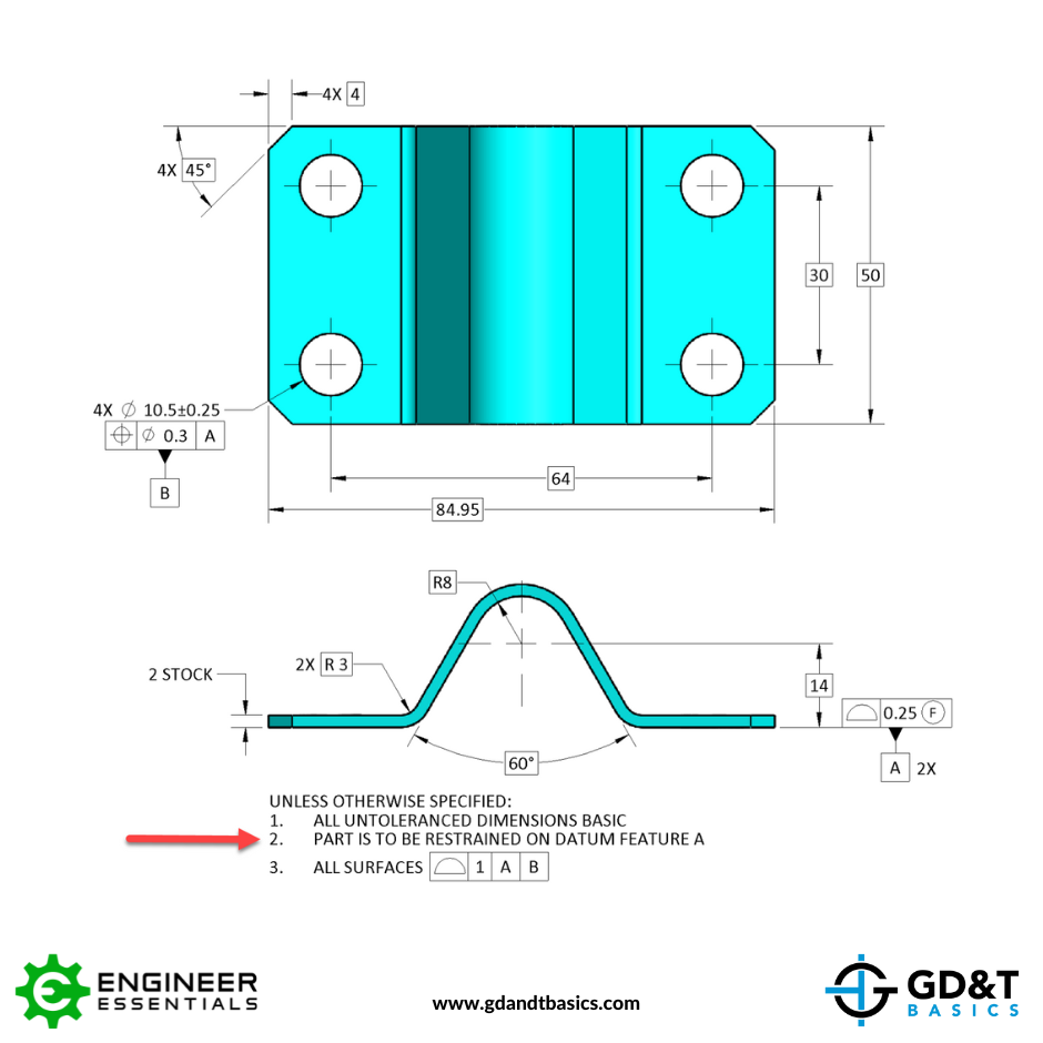
However, if the part is allowed to be fixtured or affixed with its final assembly components, it would pass as a functional part. One way to override the default “free state” is to invoke a Restrained Condition for the part. Special notes or references to documents that outline how the part is to be restrained is all that is needed to invoke this restrained condition. Occasionally, a restrained state can be applied to ensure that the assembly state of the part matches the inspected state.
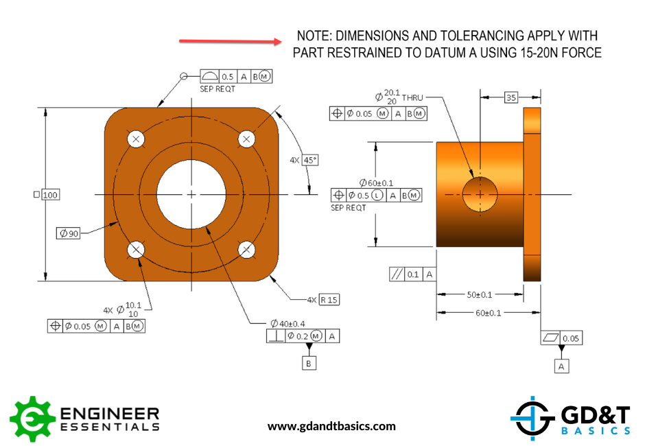
These notes and documents should give enough information to define how the part should be constrained. This can include specific fasteners, forces to be applied, methods of restraint, or information on final assembly conditions. The restraining methods should be enough to allow the part to be inspected in its desired shape. Often the restrained state mimics the state the part will reside in when it is in its final assembly state. Keep in mind that once the note is applied, the entire part is to be inspected in this restrained condition. If there are features that require inspection in a “free state” this must be specified using the Free State modifier in the feature control frame for that feature.
The one-page GD&T reference that you will use every day
A visual breakdown of every core GD&T symbol and what it controls, all on one page. Bookmark it. Print it. Actually use it.
Download the ChartAll Symbols


