
Symbol: 
Definition:
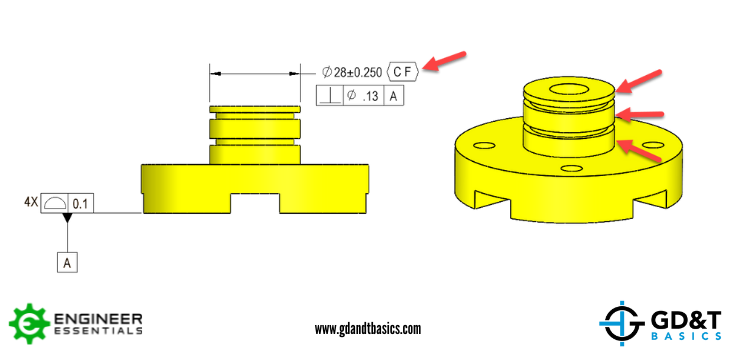
The Continuous Feature Symbol is used to indicate that a group of disjointed features or surfaces are to be considered as one continuous feature. Rule #1 and any geometric controls will be applied to the disjointed features as if they are one feature. The symbol has differing capabilities when considering ASME Y14.5 – 2009 vs 2018.
Continuous Feature with the ASME Y14.5 – 2009 Standard:
The 2009 edition of this Geometric Dimensioning and Tolerancing standard introduces the use of the Continuous Feature symbol as it to be used on features of size. This means the feature of size in question, like the boss below interrupted by the O-ring grooves, would be controlled as a single feature. Without the Continuous Feature Symbol, these three cylinders would ordinarily be able to deform in differing directions in form and location by the maximum amount allowed by either Rule #1 or any geometric controls placed on the feature.
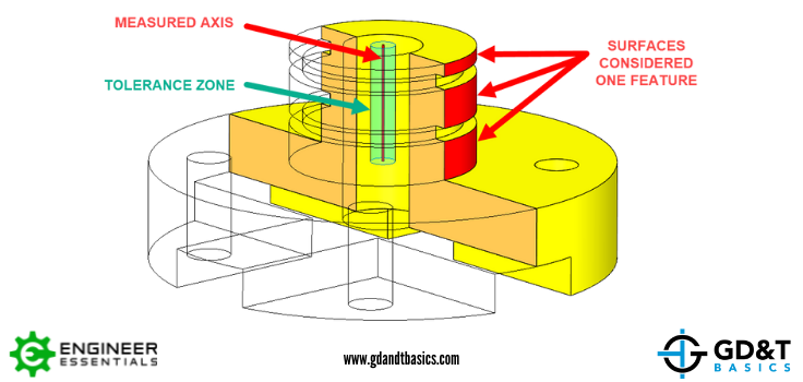
When the Continuous Feature Symbol is applied as seen above, Rule #1 would be applied to the 3 cylinders as if there were no interruption. If an additional control is applied the feature of size, for instance perpendicularity as see above, this perpendicularity would be applied to all three cylinders as if they were one cylinder. Extension lines can be used to clarify which surfaces are to be considered, however is not necessary.
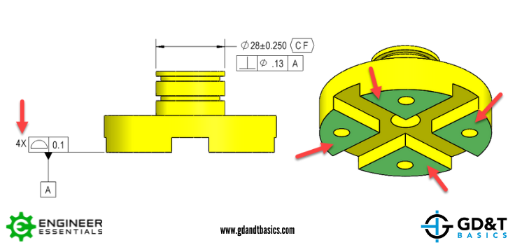
In the 2009 standard, this symbol cannot be applied to a surface in this manner. For instance, the 4 surfaces in the Figure below. The only way to control these 4 surfaces as if they were one surface would be to use the profile symbol and include a “4X” in front of it. Using this method as shown below, profile would be controlling the flatness (form) of all 4 surfaces at the same time.
Continuous Feature with the ASME Y14.5 – 2018 Standard:
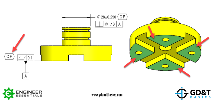
The ASME Y14.5 – 2018 standard also adopted the use of the Continuous Feature symbol however it added the ability to use it on surfaces. You can simply apply it to the feature control frame that is controlling that surface or directly next to the datum feature symbol. See the feature below as it controls the flatness all four surfaces highlighted as if they were one continuous planar surface. Extension lines and verbiage such as “ n Surfaces ” can be used to clarify the surfaces that are to be considered, however are not necessary.
Applying it to features of size is done in the same manner as previously stated and allowed in the 2009 version of the standard.
Be The Go-To Engineer at Your Company
Learn GD&T at your own pace and apply it with confidence in the real world.
GET GD&T TRAININGAll Symbols


