
Symbol: None – Always Implied default condition
Definition:
Rule #1 of Geometric Dimensioning and Tolerancing states that the form of a regular feature of size is controlled by its “limits of size.” Limits of size, or otherwise known as size tolerances, can be seen in many forms. A few of them are symmetric, unilateral, and bilateral. See Figure 1 for examples of these size tolerances. It is sometimes also known as the “Taylor Principle.”
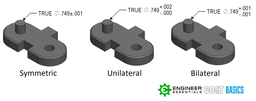
Figure 1: Symmetric, Unilateral, and Bilateral Size Tolerances
The actual surface of a regular feature cannot extend beyond the envelope prescribed by the feature in perfect form at MMC. This means that if the feature measures at MMC, the form of the feature must be perfect, which in the real world is impossible to achieve.
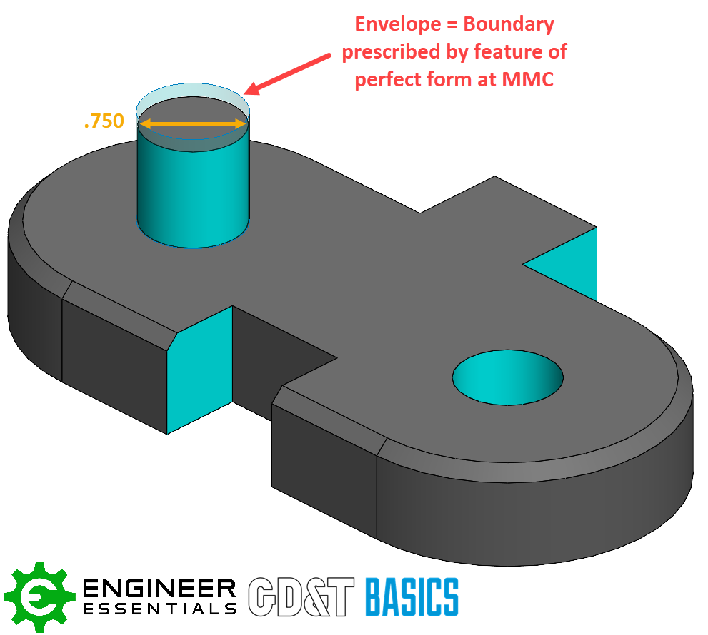
Figure 2: Envelope = the boundary prescribed by the feature of perfect form at MMC
However, as the local size departs from MMC, the form can vary up to the envelope. The combination of Size and Form cannot exceed the Envelope. At LMC the form can vary by the maximum amount.
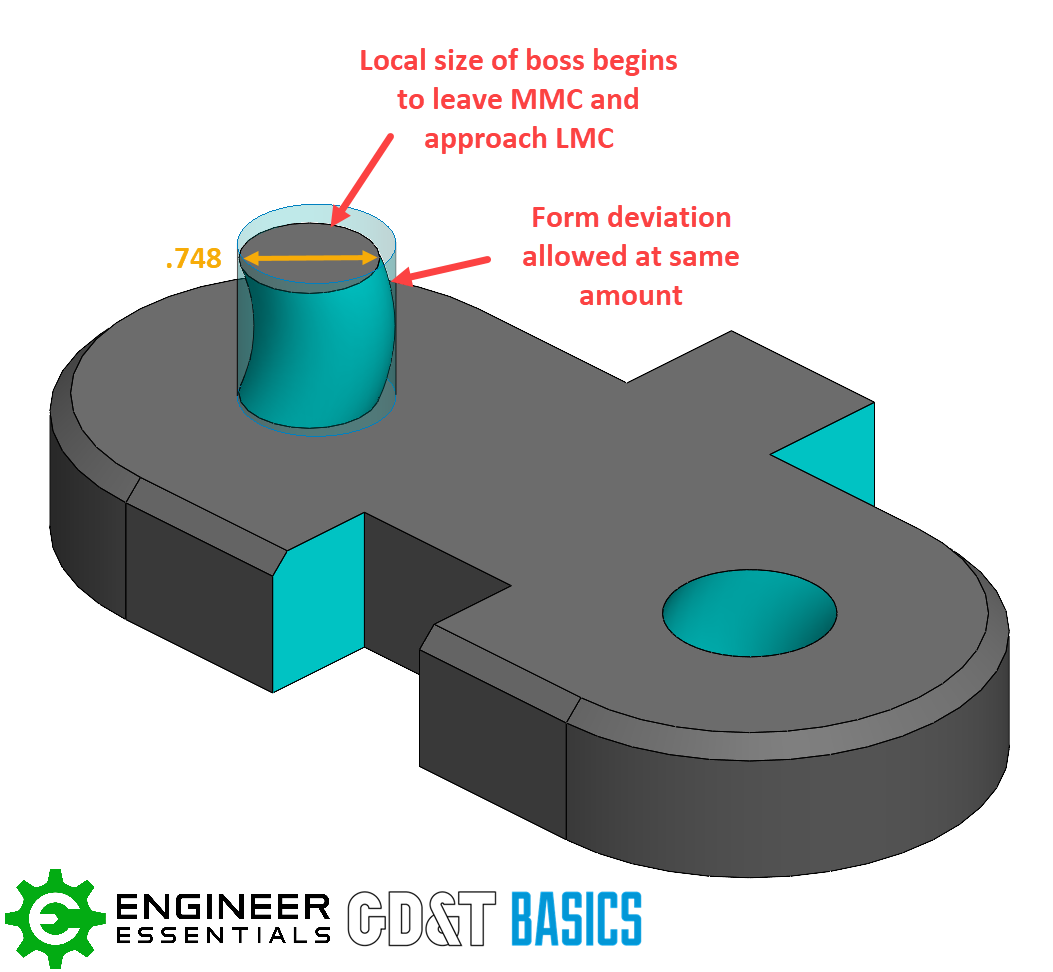
Figure 3: Form can vary by the maximum amount at LMC
The ASME Y-14.5 applies Rule #1 by default to all features of size. However certain exceptions will overwrite this rule.
- Dimensions identified as “STOCK”
- Tolerances applied with free state modifier
- When the “independency” symbol is applied to the appropriate dimension or notation
- When using “average diameter”
- Applying Flatness or Straightness to a Feature of Size
Reason for Use:
Since Rule #1 is the default condition, it is used always and ignored only when specified. Rule #1 helps fully define features of a part and ensure the form of them is being controlled. For example, the form of thru holes is typically crucial in order to accept the corresponding hardware during assembly. If Rule #1 does not control your form tight enough, a refining form symbol could be used on the feature to further restrict the allowable form deviation. Check out this article outlining how Circularity is implicated by Rule #1. Symbols that typically refine form are Straightness, Flatness, Circularity, and Cylindricity.
Additional References:
Standard Definitions
- ASME Y-14.5 2018 Section 5.8.1
- ASME Y-14.5 2009 Section 2.7.1
Additional articles:
- https://www.gdandtbasics.com/maximum-material-condition
- https://www.gdandtbasics.com/circularity-rule-1-and-how-to-report/
- https://www.gdandtbasics.com/least-material-condition
Be The Go-To Engineer at Your Company
Learn GD&T at your own pace and apply it with confidence in the real world.
Get GD&T TrainingAll Symbols


