
GD&T Symbol: 
Note: Concentricity was removed from the 2018 ASME Y14.5 standard. It is still commonly in use for those on previous versions of the standard.
Learn more about changes to the 2018 ASME Y14.5 standard.
Relative to Datum: Yes
MMC or LMC applicable: No*
* In the ISO Standards, MMC is allowed with concentricity and symmetry
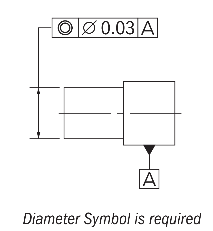
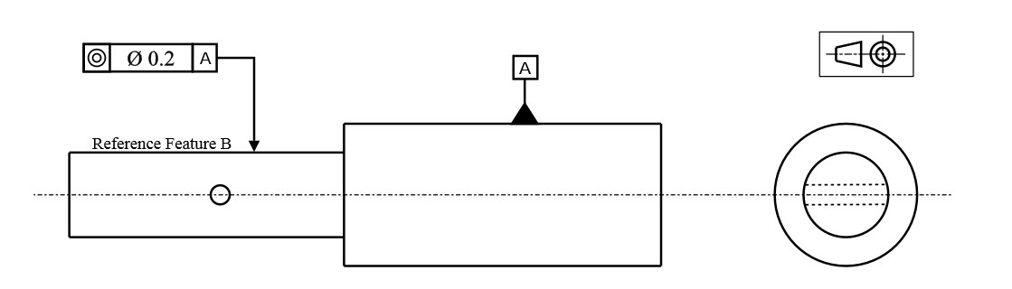
Drawing Callout:
Description:
Concentricity, (called coaxiality in the ISO Standard), is a tolerance that controls the central derived median points of the referenced feature, to a datum axis. Concentricity is a very complex feature because it relies on measurements from derived median points as opposed to a surface or feature’s axis.
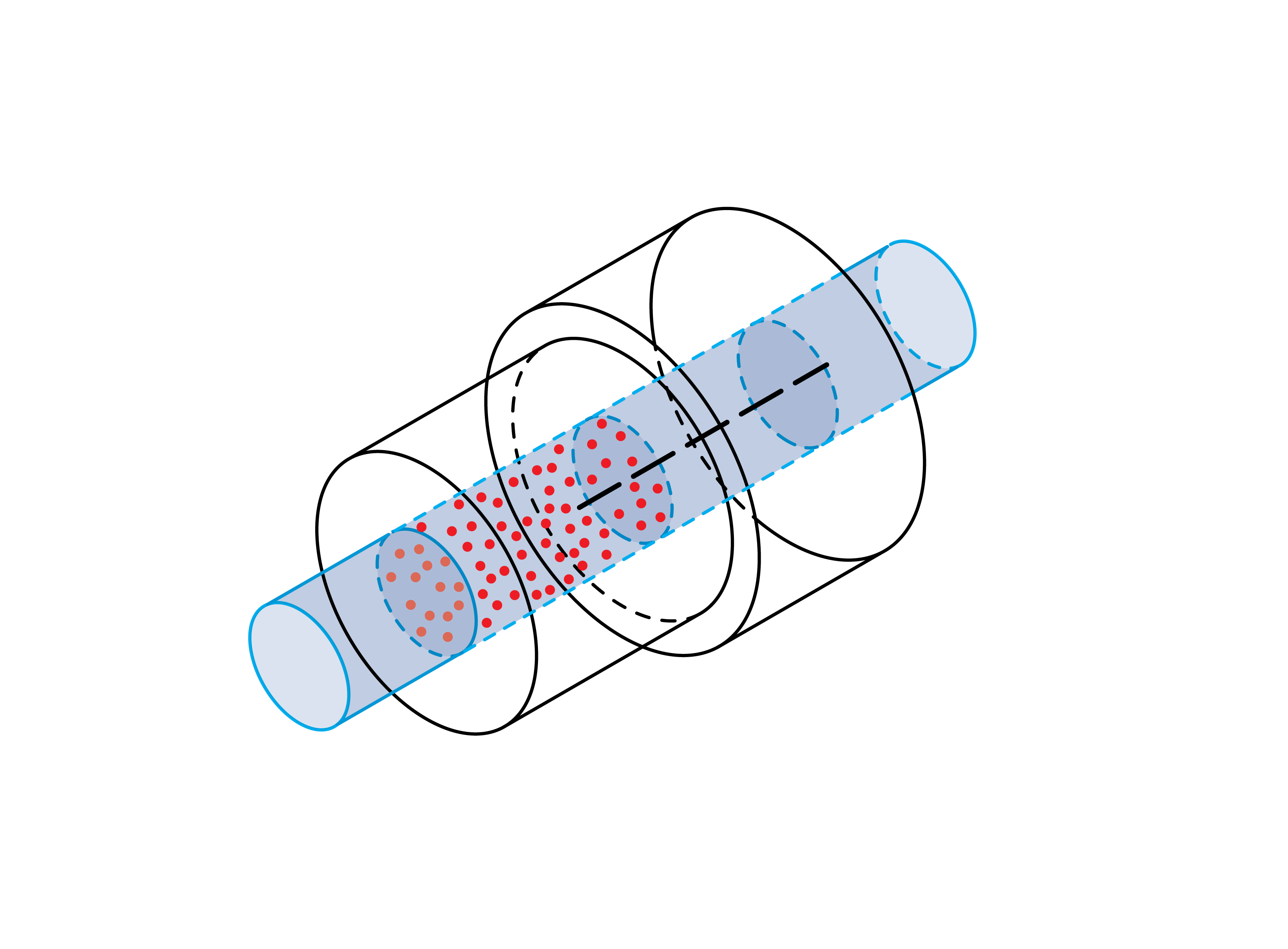
GD&T Tolerance Zone:
Concentricity is a 3-Dimensional cylindrical tolerance zone that is defined by a datum axis where all the derived median points of a referenced cylindrical feature must fall within. All median points along the entire feature must be in this tolerance zone.
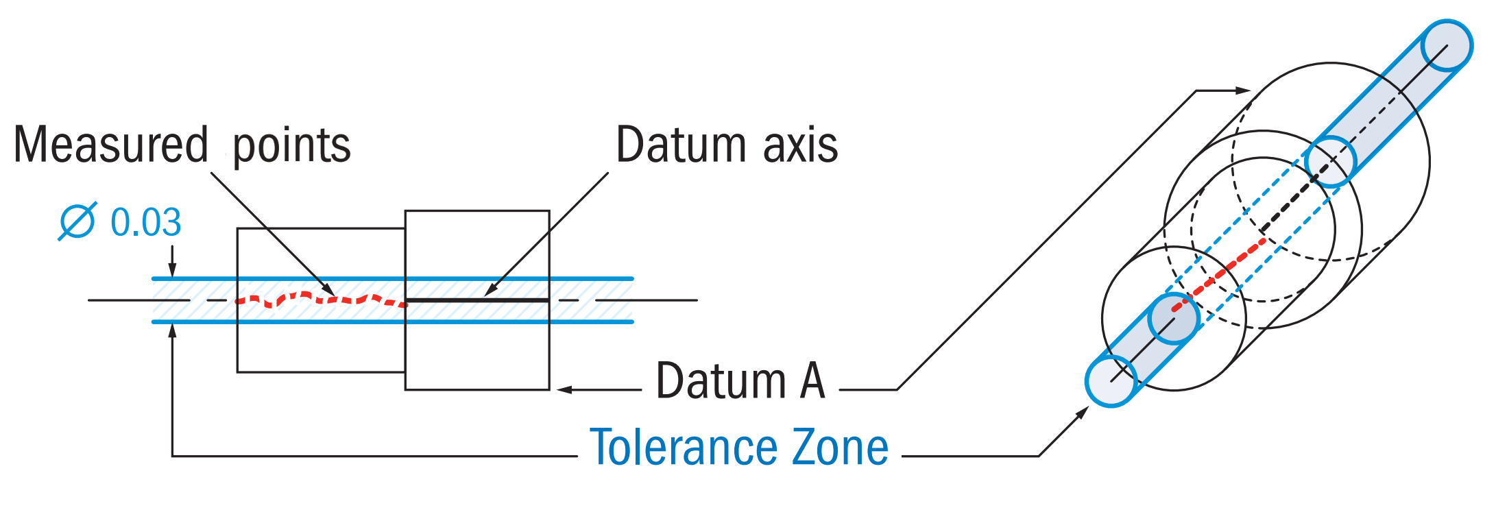
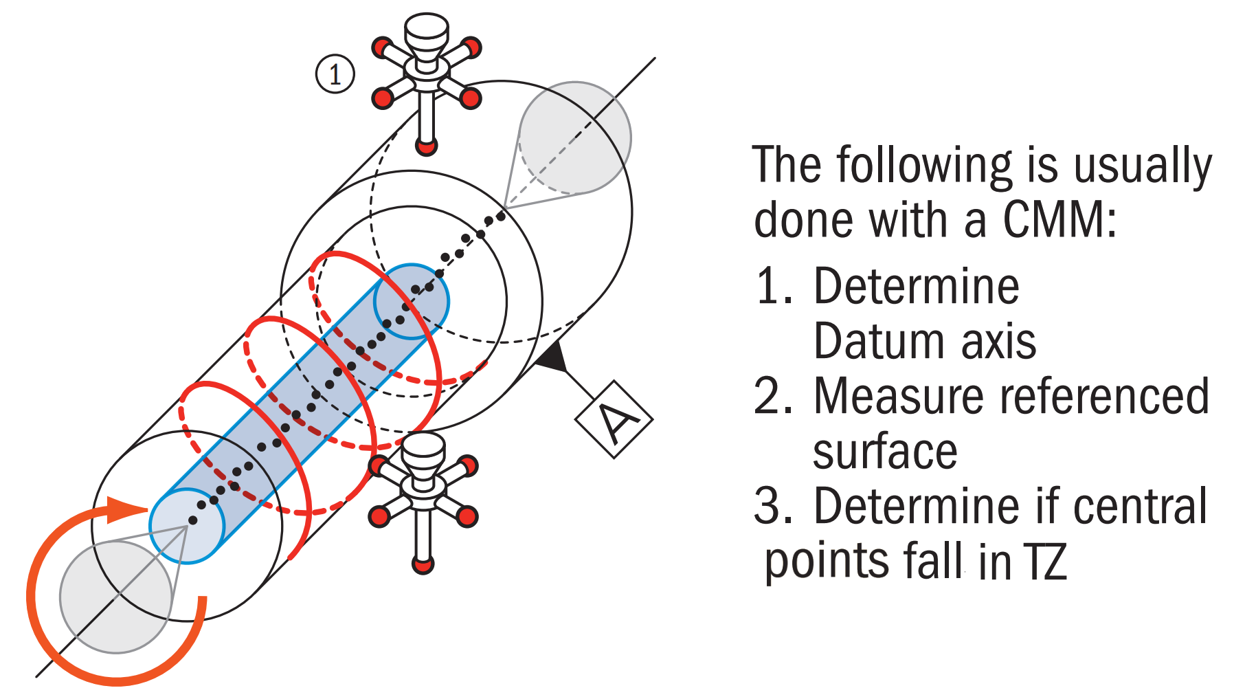
Gauging / Measurement:
Concentricity is considered one of the most difficult Geometric Dimensioning and Tolerancing symbols to measure, due to its difficulty in establishing the midpoints of the feature. First, you must establish a datum axis which to measure, Once the datum axis is established you must now take measure many a series of cross-sections (however many is realistic) to establish “diametrically opposed” (surface points directly opposite from each other across the diameter) surface points. The median points of these diametrically opposed surface points must then be mapped out for the entire feature. Finally, these points are compared to the tolerance zone established by the datum axis. This can only be done on a CMM or other computer measurement device and is quite time-consuming.
Relation to Other GD&T Symbols:
Concentricity is considered the “circular” form of GD&T symmetry. Both tolerances measure derived median points compared to a datum plane/axis and are notoriously difficult to measure.
Runout is a combination control that can indirectly control concentricity and circularity simultaneously.
e.g. If a part is perfectly round (perfect circularity), the runout measurement will equal the concentricity, if the part is perfectly centered (perfect concentricity) the runout will equal the circularity.
Concentricity is similar to position, however is not the same. While Concentricity controls the derived median points (imperfect and scattered) of surface elements, position will control the axis (perfectly straight) of the feature.
When Used:
Due to its complex nature, Concentricity is usually reserved for parts that require a high degree of precision to function properly. Transmission gears, which need to always be coaxial to avoid oscillations and wear, may require concentricity to ensure all the axes line up correctly. Equal mass or inertial concerns are one of the leading causes for the concentricity callout, however are often better designed with runout. In fact, in most cases, the use of runout or position should replace the need for concentricity and be much easier to measure.
Example:
An intermediate shaft in a transmission is composed of two different cylindrical sections which are coaxial. Datum A (right) is the drive side and relatively fixed with bearings to the housing, The referenced surface B is desired to be concentric with Datum A to avoid oscillations at high speed.
Two gears with the concentricity callout.
Concentricity would require side B to be measured in all dimensions several times to obtain a full dimensional scan of the surface of the reference feature. This scan must then be analyzed to determine the derived median points at each location along the cylinder fall within the tolerance zone. The tolerance zone would be established by the datum axis derived from datum feature A. All central points would all need to fall into the cylindrical tolerance zone to be in tolerance. This would all be done with a CMM and measurement software and required special measurement programs to compare the axes.
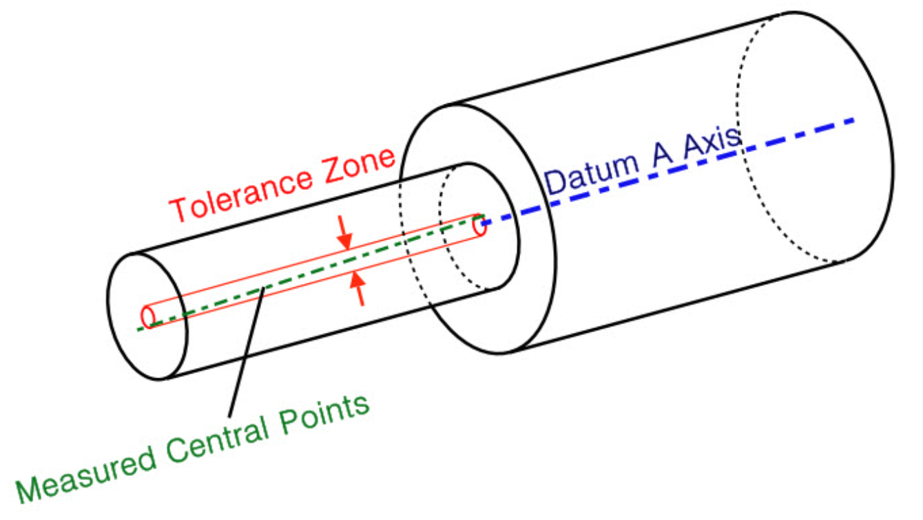
In this example, the measured derived median points (green) all fall within the cylindrical tolerance zone surrounding datum axis A, ensuring a smooth, near-perfect rotational system. Note that the derived median points do not need to form a straight line and may be scattered due to imperfections in the surface. However, as long as they all fall within the tolerance zone the part is in spec.
Final Notes to Remember:
Avoid Concentricity!
You will always hear from most machinists, measurement techs, and designers to avoid concentricity like the plague. Unless it is absolutely necessary to control the distribution of mass around a part’s median points you should look to other more applicable GD&T symbols. A good replacement for concentricity is Circular Runout or Total Runout since they compare the actual surface of a feature to a tolerance zone, while concentricity relates the derived median points of the surface to a tolerance zone. You can physically touch and measure the surface of the part to obtain a runout measurement. Controlling runout will also control the concentricity to the same extent. (Runout = Concentricity + Circularity)
Use in Ammunition Measurement
Often you will see “concentricity gauges” that are applied to homemade bullet casings. These gauges, however, do not measure concentricity but instead are measuring runout. However, since runout is just a combination of circularity and concentricity, you can technically say that you are measuring the concentricity as well indirectly.
Be The Go-To Engineer at Your Company
Learn GD&T at your own pace and apply it with confidence in the real world.
Get GD&T TrainingAll Symbols


Hi, I see on another site that Concentricity was phased out in 2018 from Geometric Tolerance.
Does anyone have information on that?
Remember also that Concentricity is realised differently , depending on if you use ISO or ASME standards.
Especially while using concentricity, mentioning tolerance zone with or without diameter symbol, which is the correct one( with or without diameter symbol) which gives complete & correct meaning to use concentricity ?
Nagaraj –
I would urge caution against using the concentricity control except in a very specific set of circumstances. It’s a difficult control to machine and inspect when you can achieve similar results through either position, profile or some combination of the two. That being said, if you do use it the diameter symbol is required to be in the feature control frame.
Hope this helps, cheers!
Matt
Where can i find the concentricity specifications for a round plastic bottle? Trying to appease a customer that states our bottles won’t label correctly even though there was no specifications.
Thanks,
John –
I’m stumped by your question. I doubt such a specification exists. If it does, I’m unaware of it. I don’t believe that concentricity would be a good control for what you are describing. In fact I would urge caution against using it as it is difficult (read costly) to meet in manufacturing and equally as difficult to inspect. Unless you have a need to precisely control the distribution of mass about an axis as in a part that is spinning at high speed you can achieve your desired results through one of the other controls like position or profile.
I know this doesn’t help your specific question, but I hope that it helps with your general understanding of the concepts at play.
Cheers,
Matt
I have a sketch of a structure composed of three sheets metal, one of them is used as based, and the others are above of this one, separates for a specific distance, these two have an orifice plate with the same diameter and they are concentrics. When the welding is applied to the structure, then the assembly will have distortions, and the two orifices plates won’t be exactly concentrics. I would like to know if there exist a minimum tolerance between hole to hole applying welding procedure. For any assembly with the same specifications.
Hi Matt,
Per ASME Y14.5 if you were to use concentricity of 2 diameters to zero maximum material condition. What does this exactly mean and is it achievable in reality?
I have a print that only has a general note stating “ALL DIA’S TO BE CONCENTRIC TO .002″ T.I.R.”, but there isn’t a datum called out on the print. Would this be an incorrect callout or are all features to be concentric to one another on the print?
Steve –
Wow, there’s quite a bit going on in your short statement. So here’s the deal, the callout on the print isn’t technically correct per ASME Y14.5. I often encounter this and it becomes a game of trying to interpret what the drafter/engineer actually meant. The good news is that in your case it seems to be pretty straightforward.
First, in case you haven’t figured it out, T.I.R. means Total Indicator Reading (at least I strongly suspect it is in your case). Second, I hope that your part is rotating or spinning. Concentricity is frequently mis-applied when either runout or position can do the job. The problem is that concentricity is a difficult control to machine and even harder to inspect. Lastly, yes, there should be a reference datum to which the control for the other features is applied.
However, I believe the designers intent was to say that he/she didn’t care to pick a primary datum, they just wanted to control either the coaxiality of the two diameters, the distribution of form about the axis or both.
I hope this helps. Please come back and ask more questions.
Cheers,
Matt
How to make sure that the two cylinders affixed will have the same axis? Is there any way besides using cmm
Ahmad –
It sort of depends on what control was placed on one cylinder with respect to the other. Did you use runout or total runout, position etc.?
One method for inspecting runout is to place the reference diameter into a V-block with the measured diameter cantilevered in space. Place a dial indicator on a height block with the probe tip directly over the measured diameter. Set the dial to zero. Rotate the cylinders and watch the dial indicator, the difference between the maximum and the minimum value represents the runout.
Be aware in the example that I just described that runout is a composite control. Meaning that it controls circularity, orientation and axis offset of a diameter. The runout value you record may not be only as a result of axis offset, but as a result of either circularity, orientation, axis offset or some combination of all three. Note that the indicator reading would tell you maximum permissible axis offset however, if all of the error was attributable to offset.
I hope this has helped clarify things for you somewhat.
Cheers,
Matt
Thank You Sir,
Your Explanation is easily understandable.
It helps me as I am a Fresh Mechanical Engineer.
I Have seen this in precision shaft drawings before; where the the concentricity is given as dia 150/300 relative to datum A where A is a bearing bore feature (for example). I can understand 1 number…but I am not sure what the slash then another number represents.
GD and T Basics,
New to your site, but highly interested.
Help requested is manual measurement of concentricity with a V-Block Spindex. Yes, I’m embarrassed to say that we are restricted to this procedure of measurement at this time. My understanding of proper measurement is to get a test dial indicator reading on the datum axis and then the same on the protruding end without any adjustment on the part. Description of set up: V-Block Spindex / part protruding from end of v-block so that both readings (datum surface and feature surface) can be taken at the same time on the one end. My information is to take a reading on the datum, then a reading on the feature and the difference is the concentricity. Is this correct and sufficient to the limits of our procedure?
Thank you.
This sounds like you are measuring runout and not concentricity. There is no way I am aware of to measure concentricity without a computer in some way. You may want to verify with your customer if this is acceptable, because if your roundness is off a bit – it will contribute to this measurement and add more to it, since concentricity does not control the form of the part.
I have an M6 weld nut DIN 928 with a 0.4mm concentricity callout with respect to the axis of a 6.4mm bracket hole diameter the nut is to be welded to. The drawing’s GD&T standard is ISO 1101. Would it be possible to use a pin to inspect this concentricty with PASS / FAIL attribute data? After locating the datum (bracket hole’s axis), we would plug the pin in to verify whether the M6 nut’s central axis is in-spec or not. Could you please advise?
Hi Matt. I’m trying to think of an application where concentricity being specified would be the right thing to do. I realize that 99% of the time it should not be called out.
Would a spinning shaft that is not cylindrical (precludes using runout) be a justified application? Maybe one that has an elliptical shaped cross section or a square cross section.
If not could you please offer up an application where concentricity is justified?
A flywheel is a great example. You do not care about the roundness of the outside, but you want to make sure it has an even distribution of form so that it rotates smoothly. It could have dips in the surface, but as long as those dips are evenly distributed, you have a balanced part.
Hello Matt,
Could we use concentricity tolerances to dictate hole diameter tolerances? Example:-
Hole diameter :- 5.2mm -0/+(not define)
Concentricity tolerance:- 0.1mm
New hole diameter tolerances after consider concentricity tolerance:-
5.2 – 5.25mm
Saiful –
Ugh, I don’t think I would recommend going down this route. Concentricity is an often misunderstood and mis-applied symbol. Most of the time when people say they want concentricity they really mean position. Why? The GD&T definition of concentricity is not the same as the dictionary definition. Concentricity as it applies to GD&T is all about distribution of mass from a cylindrical tolerance zone as defined by some datum. Concentricty is determined by measuring the median points of diametrically opposed elements. Unless you have a requirement for finely controlled distribution of mass (as in a spinning part) I would strongly encourage you to use your standard hole sizes and positional tolerances.
I hope this helps clear things up a little bit.
Cheers,
Matt
What is the formula to work out coaxility? Thanks
Nathan –
Can you provide any additional information? I’m not really sure what you’re trying to achieve.
Matt
Imagine a set of pieces that resemble a donut cut like a pizza, then add them movement from their individual center to the outside (like a cnc chuck). My internal client ask me to add to the drawing a concentricity tolerance between internal (that deforms the product) and external radius (where the piece lands in the machine). Im very new in this job and not sure if its correct measure concentricity between two radius, may you help me or advice me a bettter form to secure that the pieces will form a circle?. Sorry about my poor english 🙁
J –
I think I understand what you’re talking about, but I’m not sure what problem it is that you’re trying to achieve. I’ll caution you against using Concentricity excessively. It isn’t the same as the dictionary definition of concentric. The GD&T definition has requires that the median points of all diametrically opposed elements be within the specified tolerance zone. This has an effect on the mass distribution of the part. Typically, concentricity is reserved for components that are rotating or other situations where an even distribution of mass is required. Normally, when people say they want something either concentric or symmetric another control such as position can be used to achieve the same result more easily (and thus cheaply).
If you can provide any more information I’m happy to review and provide any insight that I can.
I have a different opinion as far as applicability of MMC for concentricity. Imagine a sleeve with two coaxial diameters of, say, 50 +0.1 and 70 +0.1 mm. Imagine a plug with two coaxial diameters of 50 -0.1 and 70 -0.1 mm. Imagine that the plug is expected to fit in the sleeve. Now the permissible limit for concentricity at the plug ( assuming the sleeve to be perfect ), shall work out to be 0.0 mm, but if both diameters are at MMC. Can the permissible limit get changed to 0.2 mm at LMC of the plug? If no, why? If yes, then MMC should be admissible. Please comment.
Prakash –
So concentricity is a control that is not allowed to use either MMC or LMC as material modifiers within the feature control frame. As far as why this is the case is due to how the median points of two diametrically opposed elements (i.e. two points 180 degrees from one another) are determined. You are essentially taking the midpoint or half the total between two points and comparing it to your reference axis. If, as you say, we use MMC then the bonus tolerance is in effect and your tolerance zone would grow resulting in a step function of varying diameters rather than a cylinder. This would allow for abrupt changes in the surface of the part.
Concentricity is sort of like symmetry for cylinders. It cares about the form and the distribution of the material but does not control the magnitude. In GD&T, concentricity does not just mean located coaxially. As an extreme example the plus sign (+) could be considered concenetric if your tolerances of size were large enough. Why? You have opposing elements that are equidistant from your reference axis. The only caveat here would be that you still have to meet your dimensional limits of size.
Lastly, I would like to urge caution against overuse of concentricity. Typically it has a few unique applications in industry where precise distribution of mass is required like when a part is rotating at high speed. Before calling out a concentricity control on your drawing consider using either position or runout.
I hope this helps, let us know if you have any additional questions.
Cheers,
Matt
Thanks a lot Matt. However a question still remains in my mind is as follows. If the stepped plug I mentioned earlier carries specific diameters of 49.9 mm and 69.9 mm, reasonably cylindrical, and asking only for a fitment in the mentioned sleeve; then on what logical grounds will it be right to insist upon concentricity of 0.0 mm? What will be faulty to accept a plug to have an error in concentricity, say, of 0.15 mm?
What is the difference between Axial Straightness vs. Concentricity? Both use the derived axis for the tolerance zone. Can a shaft (or hole) meet an Axial Straightness requirement, but not an equivalent Concentricity requirement? Is one more stringent than the other?
Concentricity is tied to a datum and controls the location of the derived median points. Straightness is not tied to a datum and controls the form of the derived median line.
Can cylindrical tolerance be applied only to stepped cylinder? or can even it be applied to assembly of two cylinders?
Thanks,
Shrenik –
Yes and no. Depending on what your actual question was, I’ll try to explain:
You can apply cylindricity to any number of cylindrical surfaces, there is no limit. Whether that’s a single cylinder or a stepped cylinder as you describe. For multiple surfaces you would just have to have multiple leader arrows pointing to desired surfaces. So in this instance yes.
However, the same tolerance controlling a cylinder of 5mm could not be used to control a cylinder of a different diameter. Don’t forget that you are still held to your limits of size. So, in this instance no.
Lastly, I’ll state that you can apply the concepts and principles of GD&T to assemblies as well as individual piece parts. There are no limitations on this either.
I hope this helps clarify a few points for you. If you have additional questions please don’t hesitate to ask.
Cheers,
Matt
Explain briefly how concentricity could be achieved whichever method of holding the
component on the lathe
Felix –
First, I’ll caution you against overuse of either concentricity and symmetry. They are often misunderstand and frequently mis-applied when another control would suffice. I urge caution as concentricity can be difficult to achieve during manufacturing and inspection and thus more costly. In the case of concentricity you might look to either total runout or tolerance of position (at RFS) first. As a general statement, you should only consider runout and concentricity for parts that are spinning (i.e. driveshafts etc.).
Now, on to your question: As for how to inspect it, my immediate answer is to do it with a CMM. To do otherwise is a pain unless you have specialized equipment such as found here: http://concentricitygage.com/index.html
The concept, generally speaking, is simple enough. It requires two diametrically opposed measurements where the local radius from your datum axis can be determined. By taking the average of these two measurements and subtracting it from one of your local radii you are determining the mid-point. As you rotate through a whole 360 degrees you are creating a cloud of mid-points. In order for the part to be ‘in-spec’ all of your points must be within the zone defined concentricity tolerance defined in your feature control frame.
I hope this helps. Let me know if I can be of further assistance.
Cheers,
Matt
I am looking at an old drawing from a very respectable British company and they repeatedly use concentricity tolerance callouts in which two reference datums are given: (1) Another diameter in the part, (2) A plain surface which is perpendicular to the diameter. Does anyone know what could be meant by this?
Ariel –
To be honest I haven’t. It’s not part of the ASME spec, I’m wondering if it may be part of the ISO standard, especially in light of it being with a British company. That being said, I see mis-application of controls all the time and frequently I am left trying to interpret what they actually meant.
With that said, here would be my interpretation: They want to use the cylindrical datum as a primary reference that sets up the tolerance zone and then they are further refining the TZ by stating it must be perpendicular to the flat surface. This could in effect, make your zone smaller if the cylinder was off by some angle to the flat surface.
I hope this helps. Try and grab a copy of the ISO standard and see if there is anything in there on the subject. There just isn’t anything in ASME that allows for what you are describing.
Cheers,
Matt
can you please explain the difference between runout and circularity , total runout and cylindricity.
Nirmal –
They are all closely related. To be clear, the primary difference between runout/circularity and total runout/cylindricity is the region over which they apply. Runout and circularity only apply at individual cross sections separately, whereas total runout and cylindricity apply at all cross sections simultaneously. With that out of the way lets move on to the differences as you outline them.
Circularity – The best way to think about circularity is to draw two co-axial circles. The distance between the circles is your tolerance. Every cross section of your part must individually fit within the region between the circles. Your tolerance zone of co-axial circles is free to translate in the X, Y and Z axes but may not tilt to fit the part (i.e., not constrained to any datum)
Runout – Think of runout as located circularity, as it must be constrained to a datum.
Deltas: Circularity is only controlling the form of the part for individual cross sections, where runout is controlling the form, orientation and position of the same cross sections.
Cylindricity – The best way for me to explain cylindricity is that it is an extended circularity control as explained earlier.
Total Runout – Same goes for total runout, it’s just an extended version of the runout control.
I hope this helps, let me know if you have any further questions.
Cheers,
Matt
We have an assembly where a stepped shaft is moving inside a stepped hole.
All dimensions are in mm.
The stepped hole has the dimensions of Ø1.400+0.003/-0.000 & Ø1.000+0.003/-0.000. 1.400x8mm long & 1.000x2mm.
The stepped shaft has the dimensions of Ø1.396+0.000/-0.003 & Ø0.996+0.000/-0.003. 1.396x15mm long & 0.996×2.5mm.
Shouldn’t we give concentricity for such a tolerance and if yes what should be the Concentricity value for the shaft and hole to function?
Bishan –
I’m sorry, but I can’t provide application specific advice as there is too much we don’t know regarding your design. All GDandTBasics can provide is an understanding of the controls and how they work.
I can offer general advice regarding your situation. If your application is one shaft spinning within another then I would tend to agree that you need either a total runout or concentricity control as position would not be the best way to ensure fit. One word of caution would be to look long and hard at runout before using concentricity. Concenricity is a more difficult requirement to machine and therefore inspect. However, there are situations where it’s use is absolutely warranted.
I hope this helps.
Cheers,
Matt
Thanks a lot Matt,
I just wanted to make sure that you understand the requirement 🙂
Those are not rotating components.
I was confused how to fix the concentricity value for such a tolerance. When I saw the drawing with concentricity Ø0.01 w.r.t “A” , I felt that there will be an interference of 0.003mm for the maximum allowed deviation. Is it possible to have a look and let me know your opinion of possible concentricity value.
We have two dia in bolt.dai A 8.00mm and dai B 10.00mm. When we check concentricity of dia 8.00 w.r.t dia 10.00 it found 0.6mm and when we check concentricity of dia 10.00 w.r.t. 8.00 it found 0.05 mm .I can not understand why it happened. Concentric should be same w.r.t to each other.please define sir.
Rajesh –
At first glance one would expect the concentricity between the two to be the same. This would be the case in a perfect world, unfortunately reality sets in. What you are seeing is an issue with circularity. How the part is fixtured from one diameter to the other is most likely what is causing the discrepancy. Your chuck may be grabbing the high points of one diameter in a different manner than it is the other diameter.
Hope this helps.
Cheers,
Matt
Hi guys, I just want to know why we use diameter symbol for indicating concentricity two different O.D in same shaft…..
JP – With concentricity controls you are required to have either the diameter symbol or the spherical diameter symbol precede the tolerance in the feature control frame. As for why, it is because by its nature the tolerance zone for concentricity is either a cylinder or sphere.
With that said, I would urge caution against using concentricity except in specific situations. It is a difficult control to produce and measure, usually only required when a precise distribution of mass from the center axis is required. Normally, this is restricted to very close tolerance situations or where you are concerned about an imbalance such as for a rotating shaft.
Hope this helps.
Cheers,
Matt
Ok, I have an issue regarding inspecting for Concentricity on samples of extruded tubing. The inspection callout at inspection says to use the following formula; (thinnest wall/thickest wall)*100. Is it just me, or does this formula tell you nothing beyond how close % wise the two measured values are? not to mention the fact that the measurements are taken from only two points on a small cross sectional slice of the tube. Since, if I am not on crack, this formula tells you nothing about how concentric the tubing is, what would you suggest as using for a physical determination of concentricity on an incoming goods inspection? I would expect runout as being the easiest to physically measure. Opinions, thoughts?
Shawn
Shawn –
First, you’re right. Second it sounds as though a more appropriate control for what you are describing would be position. Concentricity, as it is used in the ASME Y 14.5 standard, does not have the same meaning as concentricity as we learned in geometry class. This often causes problems. To start things off, please understand that concentricity and symmetry are two often misunderstood and misused symbols. They are expensive to manufacture and inspect and can almost always be substituted by either runout, as you suggest, or position, depending on you application. Concentricity in the ASME Y14.5 standard has a very specific set of applications outside of which this control should generally be avoided. The instances where it should be used are where you care about the distribution of mass, i.e. in instances where the balance of a part is critical such as for a spinning shaft.
As for how to inspect it, my immediate answer is to do it with a CMM. To do otherwise is a pain unless you have specialized equipment such as found here: http://concentricitygage.com/index.html
The concept, generally speaking, is simple enough. It requires two diametrically opposed measurements where the local radius from your datum can be determined. By taking the average of these two measurements and subtracting it from one of your local radii you are determining the mid-point. As you rotate through a whole 360 degrees you are creating a cloud of mid-points. In order for the part to be ‘in-spec’ all of your points must be within the zone defined concentricity tolerance defined in your feature control frame.
I hope this helps. Let me know if I can be of further assistance.
Cheers,
Matt
If the datum A of a gear is the center line of the gear should the datum A of the mating shaft also be the center line of the shaft?
Don –
If I assume that the drive shaft runs through the exact center of the gear, then I would agree with your assessment. However, there are always exceptions. For instance, is there a big flange at the end of the shaft that has to mate to something else with fine precision? It really all depends on your specific application. Without knowing anything more about your part, my first inclination would be to make this your primary datum.
Thanks for taking the time to help expand our community knowledge. Come back any time and we’ll do what we can to help out.
Matt
Dear experts. I have an issue regarding on concentricity. The spec limit of concentricity between two holes is 0.1mm. I’m using turning machine to process 2nd hole while the 1st hole used as chuck clamping point. The problem is, the after machine concentricity of these to holes is unstable out of 0.1mm limit which is pretty hard to believe since the process use the same center point. Is there any other factor that may contribute to this condition?
Actually yes – Concentricity and Symmetry are the most misused symbols by designers in GD&T. They should be avoided 95% of the time. Your Position (the coaxiality) is one component of Concentricity, however it also controls the distribution of surface form. For example, a perfectly centered square part would be concentric because the part is coaxial and the form is even. However if you cut one of the corners of a square, the form would no longer be even. This would cause your Concentricity to go out even though your coaxiality is perfect.
Is it correct to use 0.05mm max concentricity on 2 holes, one with a tolerance of 0.1mm and 2nd hole with a tolerance of 0.0177?
Concentricity is a tolerance zone that locates a feature. The sizes do not matter. you are locating the one axis to a datum axis, based on the derived median points.
I have a text representation that calls for Maximum concentricity of 0.05 mm. Seems like this should be maximum LACK of concentricity. What is the proper way to state this condition? The state to use and eccentrimeter to measure valve guide to valve seat concentricity in an engine head assembly. Optimum would be 0.0 error or lack of concentricity. 0.05 mm is apparently the allowable error. I don’t think there is such a thing as Maximum concentricity. Am I right?
Concentricity tolerance is always “max”. You are calculating the amount of concentric error in your part. However, to measure concentricity according to the ASME standard is a much more complicated endeavor. You need to calculate if all of your derived median midpoints fall within your datum tolerance zone. Concentricity of 0.05 is stating that the derived median points of all your surface elements on your part fall within a cylinder of 0.05 centered on your datum axis.