
Symbol: 
Definition:
The Projected Tolerance Zone Symbol is used in Geometric Dimensioning and Tolerancing to indicate the tolerance zone of a feature is to be assessed beyond the surface extents of the feature. In most cases this symbol is used to verify that a fastener will still clear a mating part during assembly regardless of how thick the assembling part is and the orientation in which the fastener is assembled.
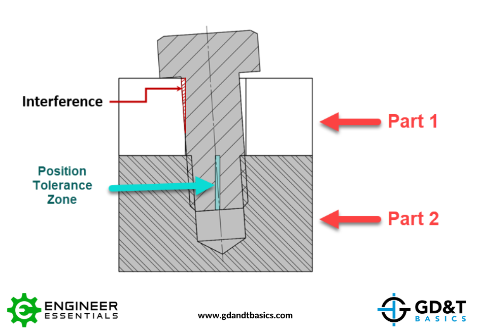
See the image below for an example of how a feature (Hole on Part 2) may remain within tolerance of position but have an interference on the mating part (Part 1) when assembled with fasteners.
Update Figure 1 below (new screenshot includes “Position Tolerance Zone”)
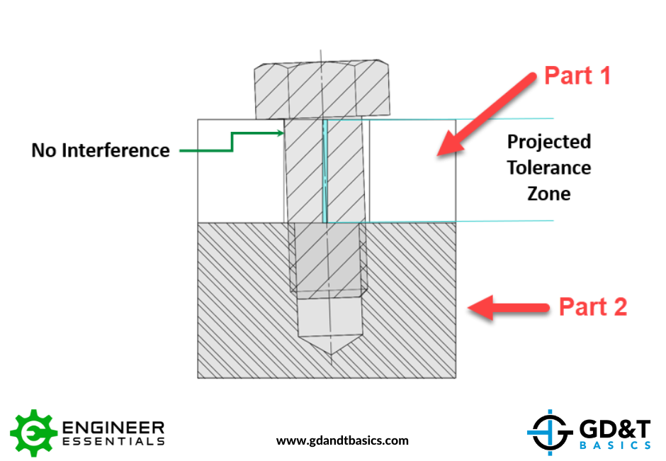
As mentioned above, one way to avoid this issue is to utilize the Projected Tolerance Zone Symbol in the Feature Control Frame for this feature. By utilizing the Projected Tolerance Zone Symbol, the tolerance zone is now assessed at a projected distance from the surface the feature is associated with. See the image below.
Applying and Interpreting the Projected Tolerance Zone Symbol:
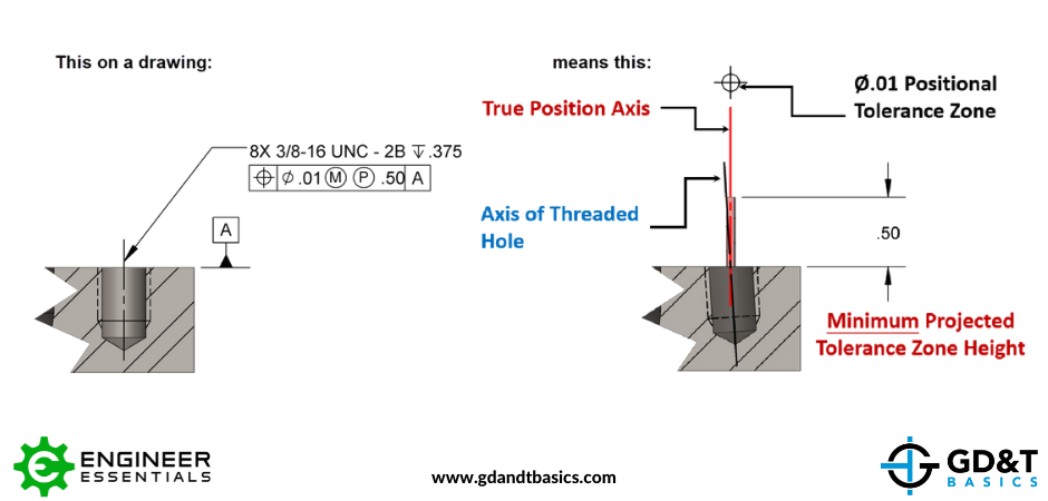
Projected Tolerance Zones can be applied to a drawing in two methods. Both methods require the symbol be placed within the feature control frame for the feature in question. The symbol is to be placed after the tolerance zone size and any material modifiers if applicable.
In the first method, a value is placed after the projected tolerance zone symbol. This value is the minimum projected tolerance zone height.
In method two, a dimensioned value with a heavy chain line drawn adjacent to an extension of the center line of the hole will dictate the minimum height of the projected tolerance zone. This method is typically preferred when the threaded feature is a thru hole, or the direction of the projection is unclear.
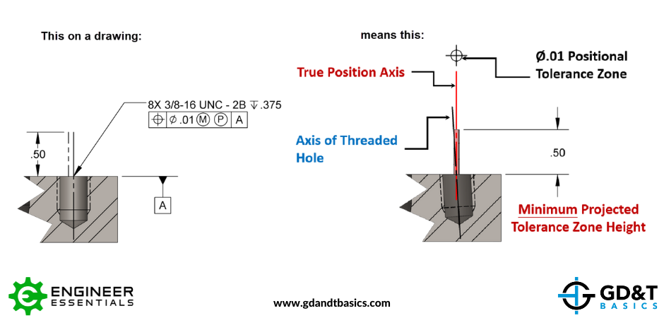
At this height, for both scenarios, the projection of the measured axis for the feature in question must lay within the designated tolerance zone. The projected zone height should always be at least equal to the maximum thickness of the mating part.
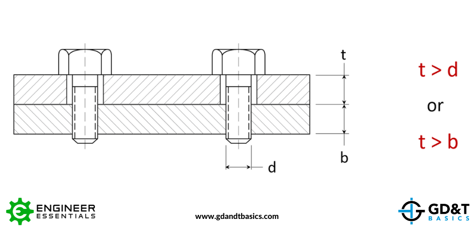
There are two rules of thumb for when to apply or not to apply the projected tolerance zone symbol to a feature. First the symbol should be applied when a mating part with a clearance hole has a thickness greater than the diameter of the bolt or pin being used. And second, the symbol should be applied when the thickness of the mating part (clearance hole) is greater than the thickness of the bottom part (tapped hole).
The one-page GD&T reference that you will use every day
A visual breakdown of every core GD&T symbol and what it controls, all on one page. Bookmark it. Print it. Actually use it.
Download the ChartAll Symbols


