
Symbol: 
Definition:
The Datum Target Symbol in Geometric Dimensioning and Tolerancing is used to define a specific point, line, or area to be used in order to establish a datum on a drawing. The symbol is defined by a circle divided horizontally in half. The lower portion contains the letter associated with the datum it is defining followed by a sequential number (starting at 1) for each datum target. The upper half of the symbol is left blank if the target is a point or a line. If the target is defining a target area, the size and shape of the area is defined in the upper half.

Datum Targets on a Drawing
Datum Target Radial Line – Datum Targets identified on a drawing by connecting the datum target symbol to the feature using radial lines. Radial lines for datum targets are either solid or dashed. If the line is solid, the target is on the “near” side of the drawing. If the line is dashed, then the target is on the “far” side of the drawing.

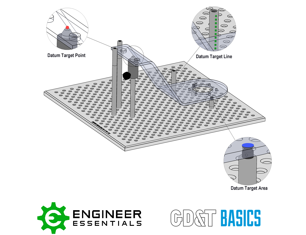
Datum Target Points (Datum Target “A3” above)
- An X-shaped symbol, referred to as the datum target point symbol, that locates a single point of contact between the datum simulator and the part.
- Dimensionally located in a direct view of the surface. If there is no direct view, the point is dimensioned on two adjacent views.
- No value in the upper half of the Datum Target Symbol
- Simulated with spherical-tipped feature
Datum Target Lines (Datum Targets “B1, B2, and C1” above)
- Shown using dimensionally located phantom line designating a line contact between the datum simulator and the part.
- The adjacent of the Datum Target Line can be designated with an “X” to show its location on the part.
- Datum Target Lines are frequently represented by using the edge of a cylindrical gauge pin.
- If necessary, the length of line can also be dimensioned.
Datum Target Areas (Datum Targets “A1 and A2” above)
- A designated area location specified on a part where the datum simulator and the part should make contact.
- Can be designated in the following ways:
- A circular, crosshatched area dimensionally located
- Full outline dimensions for non-circular areas on the drawing
- A Datum Target Point dimensionally located including the Ø size in the upper half of the Datum Target Symbol
Datum Targets in the Real World
The drawing will specify the requirements for locations, quantities, sizes, and orientations of the datum targets. The real world set up will need to mimic these requirements.
It is important to remember the 3-2-1 Rule with Datum Targets. Depending on which datum (primary, secondary, or tertiary) you are setting up, this rule will guide you as to how many points, lines or areas are required to establish a Datum Reference Frame.
Be The Go-To Engineer at Your Company
Learn GD&T at your own pace and apply it with confidence in the real world.
Get GD&T TrainingAll Symbols


