
Symbol: Ⓕ
Definition:
The Free State Symbol is used in Geometric Dimensioning and Tolerancing to indicate that a specific dimension and its associated tolerance are to be assessed in an unrestrained state. By default, all dimensions are assumed to be evaluated in a “Free State” however when the Restrained Condition Note is added to a drawing, the part is now required to be restrained. If a part is restrained, the Free State Symbol can be applied to remove the restrained condition for specific features.
The Free State symbol is often found on non-rigid components or parts that are easily deformable. The symbol is often seen being used with parts and industries that include sheet metal parts, rubber parts, plastic parts, and other flexible components.
Applying the Free State Symbol to a Restrained Part:
The Free State Symbol is comprised of the capital letter “F” circumscribed by a single circle. It is to be applied to a feature via the Feature Control Frame associated with that feature. The symbol is placed after the value for the tolerance zone size.
As previously stated, by default all parts and their features are to be assessed in their free state. However, it’s often necessary to add a note to a drawing that applies a restrained condition to the part. Often the restrained state mimics the state the part will reside in when it is in its final assembly state. See the note below requiring the part to be restrained to Datum Feature A.
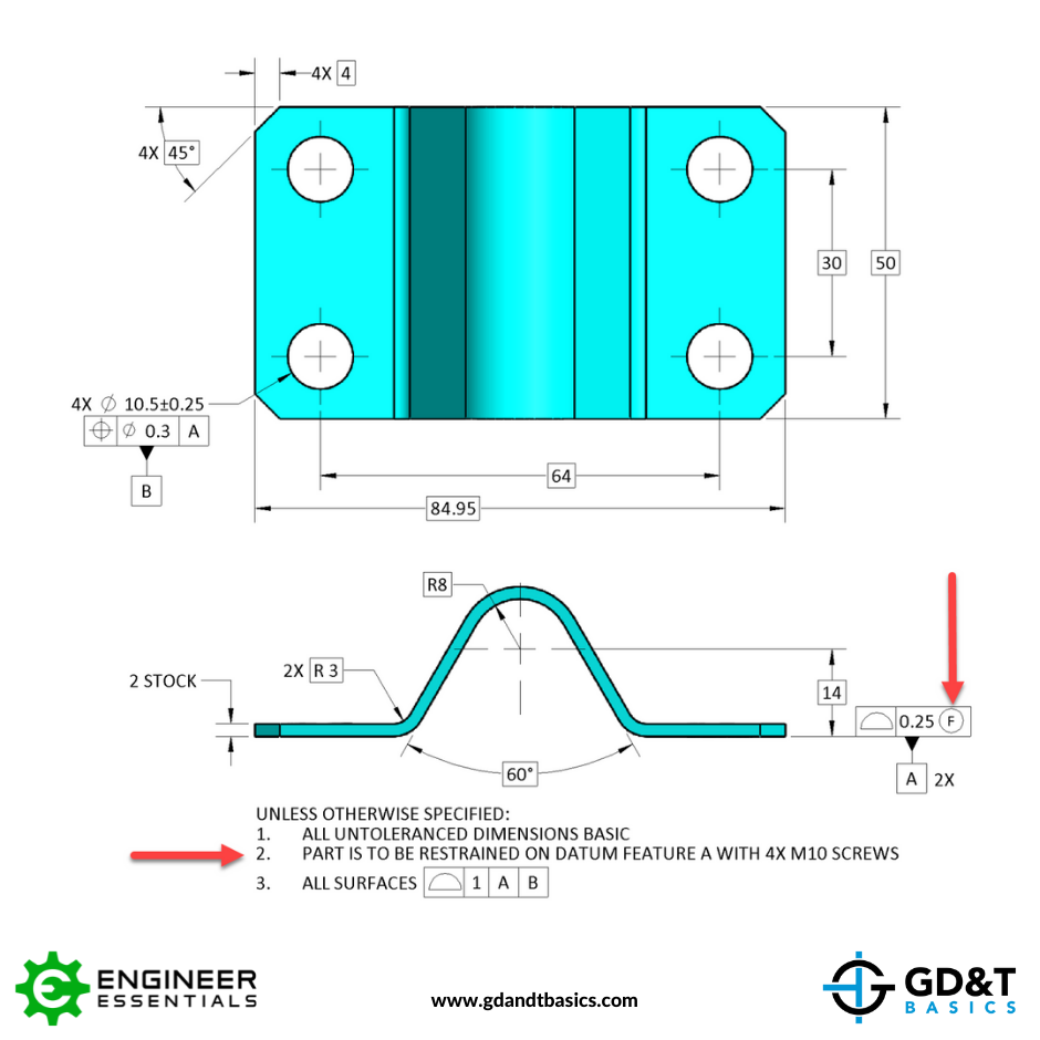
To ensure the profile of the two surfaces is inspected in its free state or unrestrained, the Free State symbol has been applied. For this example, the two surfaces indicated by the profile control will be inspected in their free state, while all other surfaces as well as the position of the 4 holes will be inspected in a restrained state as indicated by Note #2.
Applying the Free State Symbol to a Non-Rigid Average Diameter:
One unique scenario that the Free State Symbol is utilized in is when checking the circularity of average diameter. The diameters of non-rigid cylindrical parts are often held to an average diameter tolerance.
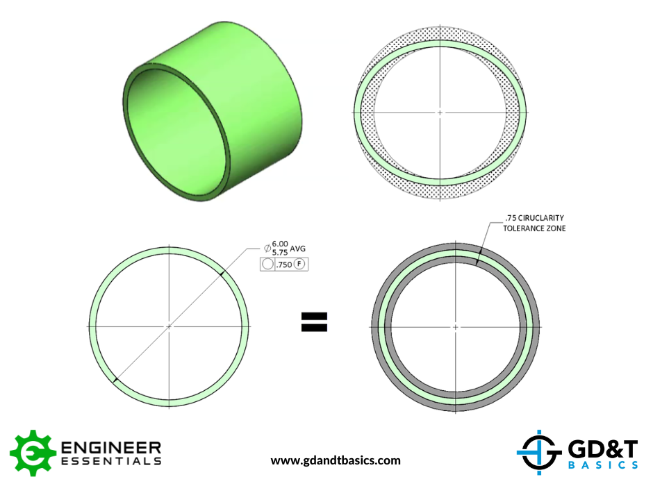
This means enough measurements are taken to establish an average diameter of the feature in question. By specifying circularity on an average diameter of a flexible part, the designer is ensuring that the part will have the correct geometry to be restrained in the desired shape when it is in its final assembly condition.
Be The Go-To Engineer at Your Company
Learn GD&T at your own pace and apply it with confidence in the real world.
GET GD&T TRAININGAll Symbols


