
Perpendicularity in Geometric Dimensioning and Tolerancing can mean two very different things depending on which reference feature is called out. The normal form or Surface Perpendicularity is a tolerance that controls Perpendicularity between two 90° surfaces, or features. Surface Perpendicularity is controlled with two parallel planes acting as its tolerance zone. Axis Perpendicularity is a tolerance that controls how perpendicular a specific axis needs to be to a datum. Axis Perpendicularity is controlled by a cylinder around a theoretical perfectly parallel axis. Pay close attention if a hole or pin is referenced since axis perpendicularity is commonly called out on these features.
GD&T Symbol: 

Relative to Datum: Yes
MMC or LMC applicable: Yes
GD&T Drawing Callout:
Surface Perpendicularity:
Axis Perpendicularity:
Description:
Surface:
Perpendicularity is a fairly common symbol that requires the referenced surface or line to be perpendicular or 90° from a datum surface or line. Perpendicularity can reference a 2D line, but more commonly it describes the orientation of one surface plane perpendicular to another datum plane. The tolerance of the perpendicularity callout indirectly controls the 90° angle between the parts by controlling the location where the surfaces have to lie. See the tolerance zone below for more details.
Note: Perpendicularity does not control the angle of the referenced feature –the tolerance is in distance units. (mm/in)
Axis:
Axis control can also be called out for Perpendicularity and is one of the more common forms of axes call outs. When it is referenced for a circular feature, the feature control frame will contain the diameter (Ø) symbol. Axis Perpendicularity can be applied to a positive feature (pin/boss) or to a negative feature (a hole). When Perpendicularity is referenced for axial control of a feature, the symbol now specifies a cylindrical boundary where the axis of the referenced feature must lie. This cylindrical boundary is formed by taking a line that is directly perpendicular to the datum feature. When this version of Perpendicularity is called out it is to be used with maximum material condition to enable easy gauging of the part. See example 2 below for how these particular parts are gauged.
GD&T Tolerance Zone:
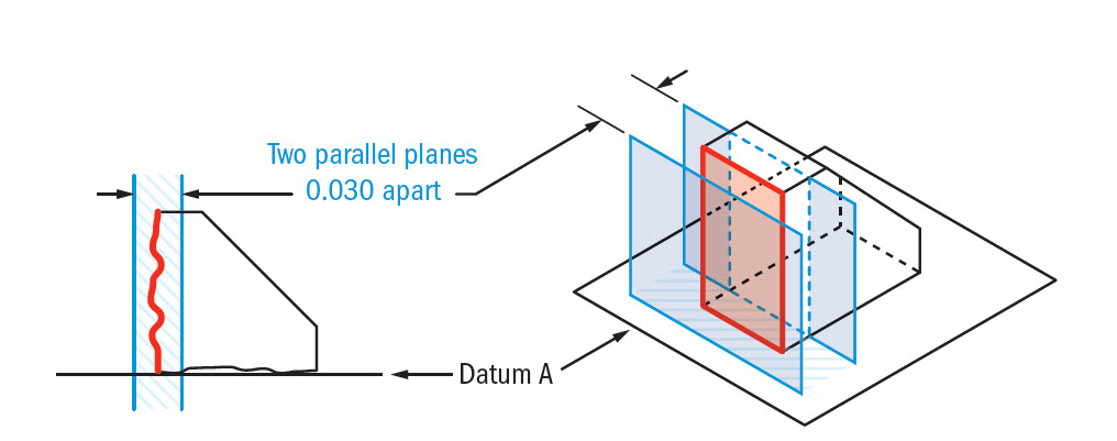
Surface:
Two parallel planes or lines which are oriented perpendicular to the datum feature or surface. The planes are held perpendicular to the datum, but only ensure that the entire feature falls into the tolerance zone.
Remember: Perpendicularity does not directly control the angle of the referenced surface; it controls the envelope (like flatness) where the surface needs to be.
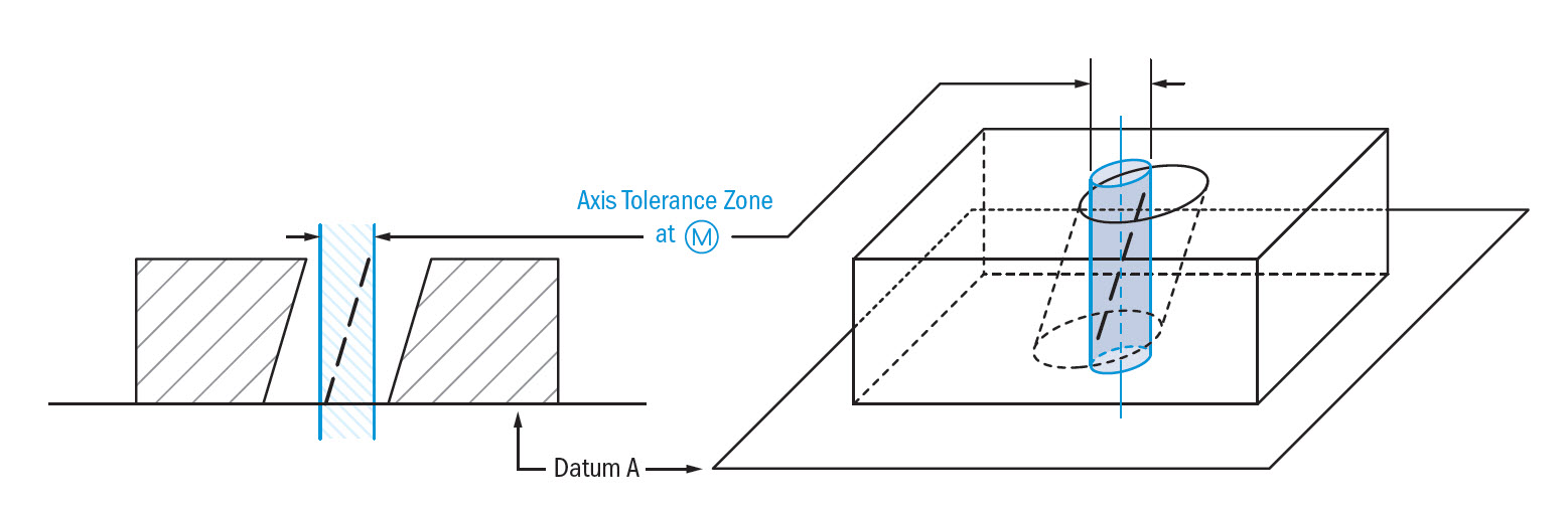
Axis:
A cylinder surrounding a referenced theoretical axis which is directly perpendicular to the datum feature. The tolerance zone is the diameter of this symbol in which the central axis of the measured feature must lie.
Gauging / Measurement:
Surface:
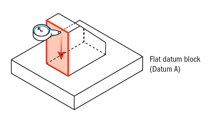
Perpendicularity is measured using a height gauge, similar to flatness, however, the gauge (or part) is locked to a 90° datum to measure how perpendicular the surface is. The entire surface has to be measured if it is a flat feature.
Axis:
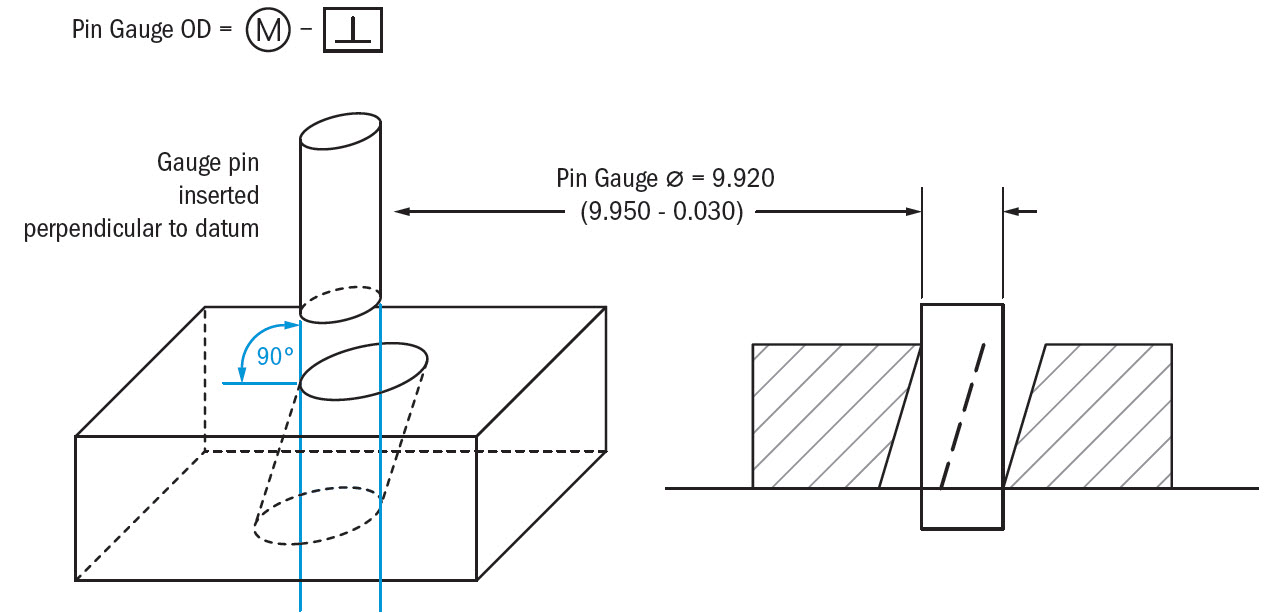
To ensure that a part or feature is axially perpendicular, Maximum material condition is most often called out on axis perpendicularity to allow easy measurement with a gauge. This allows it to be designed for either a negative (hole) or positive (pin) feature and can take into account a bonus tolerance.*
Gauge size for an internal feature (like a hole):
Gauge Ø (pin gauge)= Min Ø of hole (MMC) – Perpendicularity Tolerance
Gauge size for an external feature (like a pin):
Gauge Ø (hole gauge) = Max Ø of pin (MMC) + Perpendicularity Tolerance
See Example #2 below for a good example Axis Perpendicularity using MMC.
*Note on Bonus Tolerance:
When a functional gauge is used for Perpendicularity, any difference the actual feature size is from the maximum material condition would be a bonus tolerance. The goal of a maximum material condition callout is to ensure that when the part is in its worst tolerances, the orientation and size of the hole/pin will always assemble together. This means that if you make a pin smaller, you make more bonus tolerance for yourself. This bonus can be added to the GD&T tolerance and would widen the perpendicularity tolerance.
Bonus Tolerance = Difference between MMC & Actual condition (See Example 2 Below)
Confused yet? No worries! For more detail, see the sections on Maximum Material Condition.
Relation to Other GD&T Symbols:
Surface:
Perpendicularity is a specific form of Angularity at 90°. All of the orientation symbols (Angularity, Parallelism, and Perpendicularity) all call out the particular feature envelope referenced to a datum.
The Perpendicular Symbol is also closely related to flatness when referenced/measured surface is a surface plane. When you call out Perpendicularity, flatness is implied (you are measuring a surface variation between two parallel planes = Flatness) Perpendicularity is always measured with respect to a datum, where flatness is not.
Axis:
Perpendicularity is closely related to all the other orientation GD&T symbols when called on an axis. The tolerance zone now refers to the uniformity and cylindrical envelope of a central axis. Perpendicularity and Parallelism can be called out on holes and cylindrical pins, often with MMC added.
When Used:
Surface:
Whenever two surfaces needing a constant 90° angle, Perpendicularity is effective. Flange bearings and critical square edges usually reference it. Perpendicularity is also commonly called out on the corners of cylinders where the flat bottom must be perpendicular with the curved sides.
Axis:
Perpendicularity is very commonly called out on the center axis of a hole. Almost always, your hole needs to be perpendicular to the surface it is drilled into. When this is the case, it is called out alongside MMC to ensure that if a pin or bolt needs to be inserted into this hole, the part can enter the whole perpendicular at and always fit in. See example 2 for this explanation.
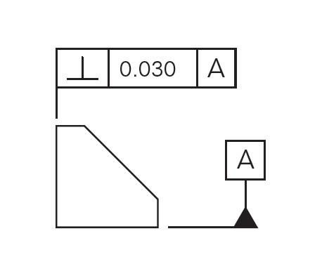
Surface Perpendicularity Example:
The edge of a stopping block for a rail must form a 90° to ensure proper mating contact takes place. The base of the block is will be our datum and the face where the stopping block makes contact is our referenced surface. To ensure that this face is always perpendicular and flat to make good contact, you would need to both tightly control the angle and the dimensional width of the part.
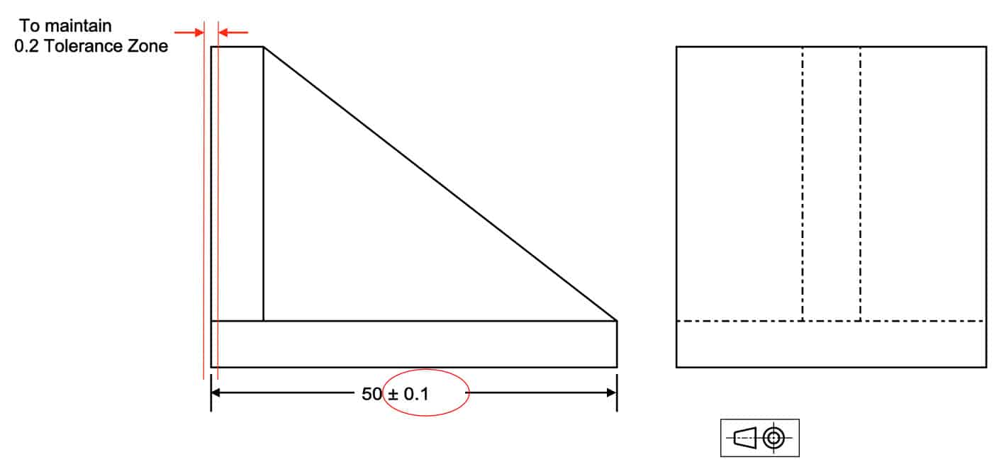
Ensuring perpendicular/flat surfaces without GD&T symbol
With perpendicularity, you can open up the width dimension and control the face’s angle containing the part very tightly. Your tolerance zone remains the same, but your part is now easier to control and fabricate.
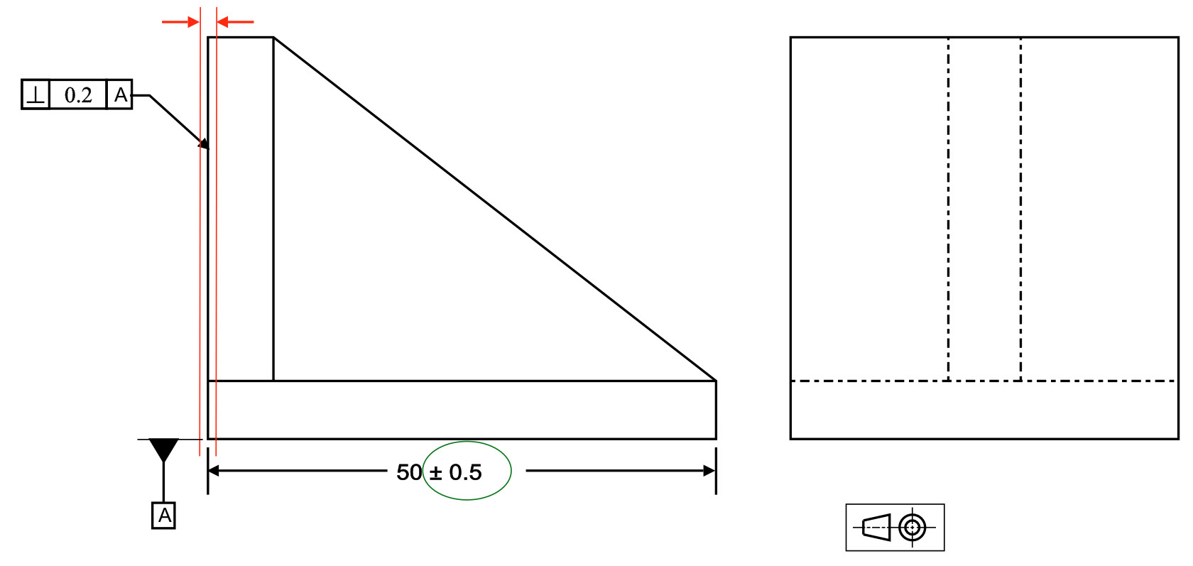
Controlling the perpendicularity with GD&T symbol.
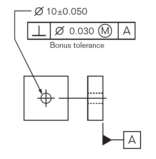
Axis Perpendicularity Example with MMC:
If you have a critical hole feature that needs to remain parallel to the surface that is formed into, perpendicularity can be called out to ensure that the hole is straight. In this example, a bolt hole is specified to remain perpendicular to its surface.

Perpendicularity on a hole under MMC
Without an MMC callout, you would need to control just the center axis of the hole and measure it to ensure it is at 90° to the bottom surface. However, when MMC is called out on the print, you are controlling both the size and the orientation of the hole. You now can check both tolerances using a functional gauge with the following dimensions:
Formula for a perpendicularity functional gauge:
Gauge Ø (pin gauge) = Min hole Ø – Perpendicularity Tolerance
Gauge Ø = 9.9 – 0.2 = 9.7
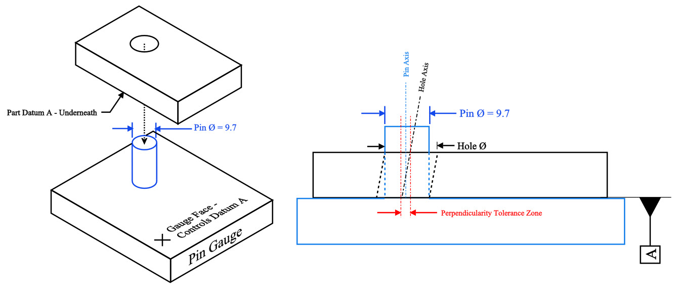
Hole Ø + Hole Perpendicularity > 9.7 (Pin Ø) to be in spec.
Due to the Max Material Condition callout, if you have a hole that is larger than the MMC of 9.9 you will have bonus tolerance that can be added on to your perpendicularity. (According to print Hole Ø cannot be above 10.1 though)
In the example below – the hole is at the least material condition (largest hole size) with the hole at the LMC, your bonus tolerance that can be added to the perpendicularity is calculated as follows:
Bonus Tolerance = Actual Part Size – Max Material Condition
Bonus Tolerance = 10.1 – 9.9 = 0.2
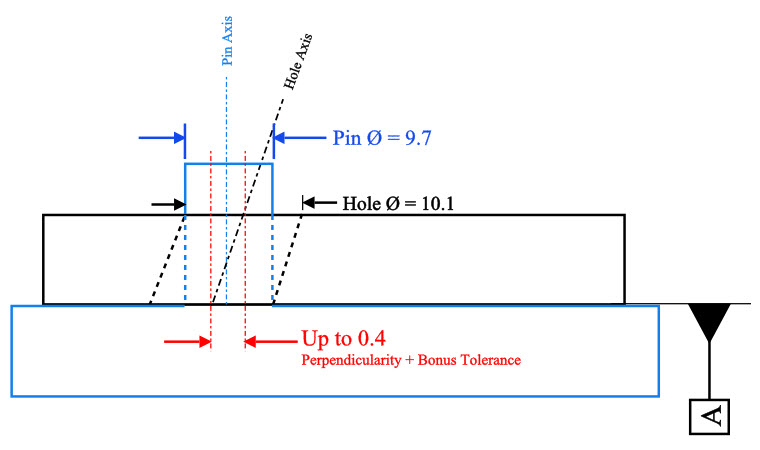
Adding this bonus tolerance to your perpendicularity means your “gauged” perpendicularity tolerance can go up to 0.4 when the part is at its largest diameter.
Final Notes:
Very Common:
Perpendicularity is very common in its surface and axis form. You will see this commonly on many mechanical engineering drawings.
Features of Size:
Perpendicularity will most likely have an MMC or LMC callout if gauge control is used in a production environment. It allows both size and orientation to be measured quickly on the line, as opposed to having to measure perpendicularity with a CMM.
Axis Controls:
Straightness, Axis Angularity, Axis Parallelism, True Position, and Axis Perpendicularity can all be called out to control a center axis. Usually, when this is a case in a production environment, MMC is also called out so that a functional gauge can be used. However, the only callouts with this case that you would see commonly are perpendicularity and straightness.
Be The Go-To Engineer at Your Company
Learn GD&T at your own pace and apply it with confidence in the real world.
Get GD&T TrainingAll Symbols


Do we have to consider the perpendicularity defined for a bolt hole while doing worst case stackup analysis??
Does perpendicularity still apply when the datum is a curved surface, not a flat surface?
Can an orientation control have three datum references? I am under the impression that it cannot for example, if I am orienting a hole on a cube (length, width and depth is not important for the sake of the example) and datum features A primary, B secondary, C tertiary are all nominally perpendicular to each other. (Simple coordinate system here…)
I came across a drawing where engineering specified this and I am under the impression that they meant position relative to ABC. I just feel it’s a super odd way of orientating a hole with respect to 3 datum feature references. I mean, I guess I can control something to be oriented with respect to three datum features but why not just call out position?
I’d like to note that the drawing has a general note, CAD model is master all dimensions not shown on the drawing are to be within .040 profile relative to ABC.
The perpendicularity tolerance is .010.
Does this mean the hole is to be located within the profile of .040 with respect to ABC but orientation has to be refined within .010 relative to ABC?
(Just an odd ball… hope I’m not overthinking it)
You are correct! orientation really could only have 2 datums to fully control u,v,w in rotation. An exception would be if something is related to a sphere (no rotation controlled) but most geometric datums, (cylinders, planes, tabs/slots) are going to control 2 orientations with and primary datum and secondary datum
Can an (axis) perpendicular control frame have a zero tolerance?
ex: perp Ø 0.00m A (-A- is a datum plane w/ cylinder perpendicular to it – Ø53.400 +0.00/-0.005 -B-)
Kim –
Yes, I suspect that what you are seeing is referred to as ‘zero tolerance at MMC’. If there is no MMC next to the tolerance in the feature control frame then there is a problem. The MMC condition invokes the concept of ‘bonus’ tolerance, wherein, as the feature departs from MMC towards LMC you gain additional tolerance equal to the amount of departure from MMC. Thus, in your example, if your cylindrical feature was produced at 53.400 the axis of the cylinder would have to be theoretically perfect to datum A. Now, if you feature was produced at 53.395, your tolerance zone would be .005.
Reference Section 6.4.4 in the ASME Y14.5 – 2009 standard for more information. Alternatively, our GD&T Advanced course has a lot of good content to help on this and many other topics if you’re interested.
Hope this helps!
Cheers,
Matt
I have a pin 1.500″ long and 0.500″ in diameter. There is a call out for perpendicularity of 0.003 at the end of the part to the datum A, which is the outside cylinder of the part. I measure this by placing the end of the pin with the call out on a flat surface and recording the Min and MAX reading at the other end of part, 1.500″ from the call out end. Is this a direct reading, or must I divide by 3 and the diameter is 1/3 of the length?
I am trying to tolerance the axis of a tapered hole in a disc. The tapered hole mounts on a rotating tapered shaft so the size of the tapered hole will have no effect on how the disc tracks relative to the rotating shaft. The goal is to have the tapered hole perpendicular to the face of the disc so there is no wobble of the disc as it rotates. I guess the tolerance I’m looking for is the amount of wobble, ie. the perpendicularity of the tapered hole to the face of the disc.
Thank you for your time,
Dave
I have an old drawing (1950’s) which is relating a flange to a bore with the note “THIS SURFACE MUST BE FLAT AND SQUARE WITH BORE WITHIN .0003 PER INCH” The flatness I understand, but how do you apply a linear requirement (.0003 per inch) to perpendicularity?
JLK –
Ha! I also have some experience with trying to interpret drawings that date back to before men landed on the moon. It’s always a bit of detective work to try and figure out what they meant. Take this with a grain of salt, but I suspect that they are trying to control the perpendicularity of the surface to the bore within a +/- zone of .0003 and vice versa. I would say that the axis of the bore must lay within that +/- .0003 zone.
This is a great example of why the GD&T system was developed. How many different ways can that note be interpreted? With a universal symbology the is clear with no room for interpretation. I’ll also go on to say that even today in my industry mis-application and flat out wrong GD&T is used all the time. With all drawings (especially old drawings) you’ve got to keep your eyes open to the bigger picture as to what the draftsman’s intent was for the drawing. You can often deduce the end result even with incorrect and improperly applied controls.
Hope this helps.
Cheers,
Matt
Hi,
I have a CMM soft dilemma, Lets say we have a block 100x100x100mm with a thru hole in center of 20 mm diameter. The frontal face of the block is datum A and the hole is datum B.
If I callout perpendicularity Datum A / Datum B it gives a value (ex: 0.1 ) and if I callout perpendicularity Datum B / Datum A it gives a value 0.02.
My question is why there is different results if I switch the callout on the same datums ?
Best regards,
3D – Student –
The answer is in your question essentially. Due to imperfections in the manufacturing process nothing is truly perfect. There is always some roughness, some angle etc. to various faces. Those datums are indicating in which order they are to contact the datum simulator: first A, then B, then C (if that’s how your datum structure is called out). Depending on the particular imperfections in the part you’ll get a different result from each setup.
Note that this is one of the fundamental reasons behind GD&T as a whole. You want consistent, repeatable results. You are telling the inspector with your feature control frame that the primary datum is to contact the datum feature simulator first, then the secondary datum and lastly the tertiary. This way everyone is inspecting the part the same way and the results will be the same. It prevents rejection of good parts and acceptance of bad parts.
I hope this helps clear things up a bit.
Cheers,
Matt
Hi,
would the workpiece thickness influence the perpendicularity of holes (I am trying to find some references or online sources which could explain that).
in my opinion, if the workpiece is thinner then it is more likely to have increase bending in the workpice during drilling which could influence the perpendicularity of the machined hole.
Regards
Khaled
Yes, that is correct, when the material will have less structural control over the piece as well. Think a piece of sheet metal with a bolt in it. The perpendicularity of the hole does not matter too much since the bolt would easily bend the sheet metal if it was at an off angle. One solution to this is functional testing or Finite Element Analysis, which could tell you the strain that the hole will have with a fastener. Location matters too since a hole that is very offset would need to have its fastener installed at an angle. Perpendicularity is usually best when the depth exceeds the diameter of the fastener as a rule of thumb.
I have a question about determining what value of perpendicularity tolerance to put on a drawing.
I have a part with a blind hole for an M5 thread-forming screw. I can determine the size and position tolerance on the hole based on thread-engagement and lining up the hole with the mating part, but I’m not sure what considerations inform the perp tolerance. Considering that the screw is about 12mm long, it will naturally align to the blind hole into which it is threading. If the hole is at a cocked angle, it could put asymmetrical compressive force on the mating part under the screw-head.
I imagine that determining the perp tolerance properly would probably necessitate calculations that involve the compressive yield stress of the mating part, the size of the screw head, and other factors, but I’m hoping there might be a simpler “rule of thumb” I can reference?
Hi
my query is on our drg. hole perpendicularity is given in value over a length. i.e 0.03/100 . Is it correct to mention perpendicularity of hole ? i think as per your guidance it should be diameter not length.
i have a cylinder product, which L is approx. 57 mm. Customer requires us to measure perpendicularity of inner diameter by using one of the end of cylinder as the datum. We do not have a CMM now. I have no idea on how to measure for this condition.
Hi,
I have a long bolt. The axis of the bolt is referenced as Datum A. A small surface is of shank is defined with 0.15mm Perpendicularity. Is this a correct definition of perpendicularity?
This datum A is now added with datum modifier. How the perpendicularity will be affected due to this datum modifier?
Matt great info!!
Quick question. Can perp of a hole to a primary datum be measured by position? Ie if I have 2 dimensions one from secondary and one from tertiary datums, but the axis is off 90 degree. Would this not show one of the dimensions out of position? Or does the perpendicularity have to be measured separately and then geometric tol calculated?
Nick (aka Spacechicken) –
Actually, perpendicularity is controlled via position which is why you will frequently see a composite control with a refinement of the perpendicularity. The way the datum structure works is that you are locating a theoretically exact cylinder at basic dimensions to your secondary and tertiary datums and perfectly orthogonal to your primary datum. Within this cylinder the axis of the hole may shift left/right/up/down or tilt as long as it remains entirely within the cylinder throughout the length of the part. It is in this manner that the perpendicularity of the feature is being restricted.
When you perform the inspection of this requirement through the use of either a functional gage or by using a CMM you are also inspecting the perpendicularity. As an example, if your part was drilled perfectly for location and size but at a 25 degree angle the axis of this hole would be out of bounds of the tolerance zone cylinder I had described earlier and the part would be rejected.
We’ve got a great introduction to the basics of GD&T, I’d encourage you to enroll and learn more. Let us know how else we can help.
Cheers,
Matt
This has been a great source of GD&T knowledge for an unexperienced quality engineer like me. I have a question regarding your axis perpendicularity examples:
Does having 0.2 bonus tolerance mean that I should now use a functional gauge Ø = 9.5? Since Min. hole Ø – Perpendicular Tolerance is now equal to 9.9 – 0.4.
This question extends to all bonus tolerance applications, really. Should the bonus tolerance be considered in choosing the appropriate functional gauge?
Aaron –
All functional gages are based off of the virtual condition. Also, remember that in order to use fixed functional gaging you have to have either the MMC or LMC modifier called out in the feature control frame. Here’s a quick rundown on what the virtual condition is for both MMC/LMC for internal and external features.
MMC
External Feature: Largest size + tolerance (from feature control frame)
Internal Feature: Smallest size – tolerance (from feature control frame)
LMC
External Feature: Smallest size – tolerance (from feature control frame)
Internal Feature: Largest size + tolerance (from feature control frame)
Hope this helps.
Cheers,
Matt
Thank you for your website and comments. I find them very helpful.
My question is this, does a perpendicularity callout (with dia symbol) for a hole feature provide control for both orientation AND location? If so, would that be the case when it just happens that you want to control perpendicularity and location with the same cylindrical tolerance zone? Wouldn’t you accomplish the same thing if a position callout was used?
Walter –
So this is actually one of the most common misunderstandings of the perpendicularity control. It does NOT control the position of a feature of size. It only controls the orientation. The simplest way to explain this is that perpendicularity and parallelism are both very specific cases of angularity. Would you be able to support the statement that either parallelism or angularity locate features of size? Same story for perpendicularity.
It is for this reason that you often see perpendicularity as a refinement of the position tolerance for features of size. The only situation I can think of offhand where you have only a perpendicuarlity control applied to a feature of size would be on datum. An example of this would be if you were specifying a perpendicularity requirement for the inner or outer diameter (as a datum) of a washer to the flat primary surface. You would then use position to locate the other diameter of the washer back to datum A and B.
I hope this helps. Let us know if you have any further questions, we’re happy to help.
Cheers,
Matt
thanks a lot Matt, that really helped. does that mean that a perfect hole would have near 0 perpendicularity or ideally zero.
I will make sure to add any updates here if I get any new information regarding the matter.
Cheers
Khaled
Hi All.,
I got some data obtained by a CMM machine for machined holes, one of the measured parameters is called PERP. I assumed it is hole perpendicularity. but I am not sure what is the unit for the data. is it in mm since the other data is in mm or is it in degrees.
sorry I am not familiar with perpendicularity before and I am trying to make a study from collected results.
sorry for asking such a questions but if for example for a hole the perpendicularity is 10 microns, what can this tell me about the hole?
many thanks
Khaled –
Perpendicularity as it applies to holes describes the orientation of a hole axis relative to a specified datum. The tolerance zone is represented by a cylinder located at the basic location. The axis of the controlled hole must then lie entirely within this tolerance zone cylinder in order to be considered ‘in spec’. So when the CMM is telling you the perpendicularity value of the hole in mm I believe it is telling you the actual as manufactured condition. To describe it a little bit better it is telling you what the smallest diameter the axis of your hole would fit in. Unless you have programmed it otherwise you’ll have to then compare the as measured value against the drawing requirement.
Use a little bit of caution and common sense here as I’m not all that familiar with CMM and inspection equipment.
I hope this helps. If you find out otherwise let us know and contribute to the community knowledge base.
Cheers,
Matt
We have a six sided block, all angles 90 degrees.
Perpendicularity of a surface relative to an adjacent surface is described as 0.00174 RAD (followed by the first surface reference letter, then the 2nd surface reference letter)
Does RAD describe the maximum variation in Radians? (so .00174 RAD is .0997 degrees?)
If not, I cannot determine how RAD is used in this case.
Any help is appreciated!
Thank you
Dillon
Dillon –
I can’t really think what else RAD would stand for other than radians. Taking the radian value and multiplying by 180/pi will give you degrees. What’s confusing here is that in GD&T all of the orientation controls (angularity, parallelism and perpendicularity) all state tolerances in terms of width between 2 parallel planes NOT degrees. Can you provide any more info? Is there a chance there is a setting in your software that isn’t what it should be?
I hope this helps. Sorry I wasn’t able to provide conclusive direction here.
Cheers,
Matt
Hi
I really Enjoy to read our GD&T Lesson,but i have doubt How you will Define Geometrical Tolerance value?
for exam
Perpendicular Tolerance value is 0.03
Ramesh –
A geometric tolerance zone is best described as: the distance between two parallel planes or lines, a sphere (very rare) cylinder or circle of diameter equal to the specified tolerance value. I’ve listed out the geometric controls and the types of tolerance zones they can use.
Flatness of a Surface – Two parallel planes
Flatness of a Feature of Size (FOS) – Two parallel planes
Straightness of a Surface – Two parallel lines
Straightness of a FOS – A cylinder
Circularity – Two coaxial circles
Cylindricity – Two coaxial cylinders
Perpendicularity of a Surface – Two parallel planes
Perpendicularity of a FOS – Two parallel planes or a cylinder if the dia symbol precedes the tolerance
Angularity of a Surface – Two parallel planes
Angularity of a FOS – Two parallel planes or a cylinder if the dia symbol precedes the tolerance
Parallelism of a Surface – Two parallel planes
Parallelism of a FOS – Two parallel planes or a cylinder if the dia symbol precedes the tolerance
Position – Two parallel planes or a cylinder if the dia symbol precedes the tolerance
Concentricity – A cylinder
Symmetry – Two parallel planes
Circular Runout – Two coaxial circles
Total Runout – Two coaxial circles when applied to a diameter and two parallel planes when applied to a surface that is 90 deg to your datum axis
I hope this helps, let us know if you have any further questions.
Cheers,
Matt
not remedy what i mean is common solution
sir,
What are commom problem why we encountered no good perpendiculary with our cnc lathe process and what are the remedy
Hello, I’ve the question on the perpendicular. Normally we measure the perpendicular of a part is placing the datum to granite table, let say the measure result is 0.1. However, when the part is to be mount on the machine (with tighten screw on the datum side), the perpendicular value is run out till 0.2 due to the flatness of the datum is not good. In this case, is it i need to specify flatness on the datum as well? Thanks.
Loh –
I’m not positive I understand your question. You do seem to have a firm grasp on how things work though. In general it is a good practice to place a flatness tolerance on planar datums to make them more stable and reliable on the inspection table. I believe this should solve your issue. I would also encourage you to look at the mating surface as well if the perpendicularity during assembly is critical. I hope this helps.
Cheers,
Matt
Can perpendicularity have 2 datum?
thanks
Shrenik –
Absolutely, perpendicularity is allowed to use multiple datums. Think of a coordinate system with X, Y, and Z axes. With these three axes you define three separate planes, that in a right coordinate system are all mutually orthogonal. Any single one of these planes can tilt while still being perpendicular to the other. It is in this sense that you can restrict or limit the angularity and perpendicularity to multiple datums.
I hope this helps.
Cheers,
Matt
I have a cylindrical part and I wish to specify the perpendicularity of the end faces. Intuitively, I want to use the axis of the part as the datum and specify perpendicularity of the faces. This seems to be the opposite of the description of normal use. Would I be in error if I followed my intuitive approach?
John –
There are two ways you can accomplish what you want. The first of which is to reference the diameter of the cylinder as a datum and then specify a perpendicularity control on the normal face. The second and more roundabout way of doing the same thing would be to use a total runout control on the normal face. The net result is the same, you’re just not used to thinking of surfaces in this way.
I hope this helps!
Cheers,
Matt
Hello, very good information from this site and well explained, I have a doubt, I have a drawing that requires to measure perpendicularity of a hole with cylindrical tolerance, but the reference datum is a cylinder (axis), the piece to be measured does not have any planes since it’s completely cylindrical (tube). Is it possible to have a evaluation of perpendicularity on a cylindrical zone between 2 axis?
Oscar –
Absolutely. The axis of one feature is based on the orientation of the other. I’m assuming that the perpendicular hole is for a pin/setscrew/bolt etc. The main axis (the datum) moves within it’s tolerance zone and has a direct affect on the lower level axis. It is theoretically located at 90 from the primary datum and is free to move within the confines of its own tolerance zone.
Hope this helps. Cheers,
Matt
We have a plane being dimensioned perpendicular to a cylinder but they also have a flatness callout on the same surface, i.e. Perp. .0005 and Flatness .0005. Based on the example above, these appear to be overlapping callouts? My initial thought was the surface must be flat within .0005 and the plane must be perpendicular within .0005, not all the individual points of the surface.
Mark –
Not necessarily and are you sure it’s not the other way around. What is the datum, the plane or the cylinder? A perpendicularity control requires the use of a datum and it’s fairly normal to throw a flatness control onto a datum to improve stability on the inspection table.
Now, in the event that it’s the plane that is being double controlled as you have it. It would appear that these are conflicting requirements, where in reality the flatness would be serving as a refinement of the perpendicularity. You are correct in that you are viewing the perpendicularity control as an oriented flatness. However, what you are forgetting is that flatness does not use any datum and is only holding the flatness of the surface relative to itself. So it’s entirely possible that you can live with your part have a surface perpendicular to within .04, but then, within that zone be flat relative to itself (the surface) to .2.
I hope this helps.
Cheers,
Matt
Hello,
If a perpendicularity specification is called out for a hole but with no symbol of diameter, and besides, the only datum is a line (not a plane), how can we proceed? How can we interpret this? Is it an axis perpendicularity? The drawing is ruled by ASME Y14.5.
Thanks a lot
Jorge –
If a perpendicularity specification is applied to a circular feature of size it must include a diameter symbol before the tolerance. This is in accordance with both ASME Y14.5 specs in common use (1994 and 2009). Not to throw stones but I believe the drawing to be in error. Further, having a single line (edge?) as a datum isn’t correct either. I hope you mean axis, this is really the only way this control works.
My recommendation to you would be to go back to the designer/engineer and ask for clarification and gently point out areas you are struggling with.
Now, as for what I think the engineer/designer is trying to achieve? I think they are trying to control the perpendicularity of the circular feature basically relative to a cylindrical tolerance zone. The thought process isn’t necessarily wrong, just the implementation.
I hope this helps, let me know.
Cheers,
Matt
What if i do not have access to CMM. I need to measure the perpendicularity of a hole. What is the old school method of doing this?
The easiest way to check perpendicularity of a feature without a CMM is through the use of a functional gage, where the pin of the gage is set to the virtual condition of the hole and perpendicular to the relevant datum reference frame of the gage. This won’t tell you the amount of perpendicularity error, but it will provide either a pass/fail check. This method is often used in high quantity production runs as it requires no interpretation, if it fits on the gage the part meets requirements, if it doesn’t, it fails. This assumes that you have the MMC modifier called out in the feature control frame next to the allowable tolerance.
There are a few other methods you can use to actually determine the amount of perpendicularity error, but they become somewhat complicated.
if there is no call out or symbol for perpendicular between a hole and surface how is a tolerance determened
Typically you ca add a general loose tolerance for perpendicularity, and Profile that apply to the entire drawing. If nothing is called out though it should be added. For an ISO drawing, there are standards that can apply a general tolerance to the drawing, but there is no such standard for the ASME y14.5
What about implied 90drg. angle hole is .500-501 dia. how is tolerance determined
Implied 90 NEEDS a tolerance of perpendicularity either in the notes, title block or on the dimension. If this is missing then it is an untoleranced dimension and can essentially be whatever you want. If the datum is the hole, then the surface needs to be within two parallel planes on the surface (of whatever tolerance (x) that is called) if the datum is the surface, then your hole’s axis needs to be within a perfect cylinder of diameter (x) perpendicular to the surface. Without a tolerance though this is wide open and ambiguous.
We have a Dwg callout of perpendicularity of Threaded collar for a bolt to be inserted ref to a Datum surface that the collar is welded onto – .50mm to datum A . There is no other indications on the dwg for bonus tolerance or any other symbol – There is a great deal of opinion as to the correct use of this symbol Vs Angle . We want the threads inside the collar to be straight to datum surface – Please advise if you can – Thank you .
The theoretical definition would be that there is an axis that you want perpendicular to a datum surface. What you are controlling with this is a cylindrical tolerance zone that is perfectly perpendicular to datum A. it can translate anywhere along datum A but not tilt. The axis of your threaded bolt must fall within this cylindrical tolerance zone that can translate along the datum surface. For Perpendicularity, the axis is derived from the Unrelated Actual Mating Envelope which is another way of saying the smallest perfect cylinder that can fit around the thread. Here is a picture for more detail:
A common misconception when people hear “perpendicularity” is they think of an angle. Angle really has nothing to do about it. You are taking an imperfect part and seeing if it fits a perfectly perpendicular size condition. Hope this helps!
Supposing you have a cylindrical feature extending off of a flat surface that you want to put a perpendicularity spec on. If I am understanding the explanation correctly, the axis perpendicularity spec defines the diameter of a cylinder that the axis of the feature must fit entirely within. Therefore, am I correct in understanding that for the same perpendicularity spec (say, 0.030 like in the given examples), the allowable angle of tilt for the cylindrical feature is also dependent on its length? i.e. a short cylinder could be tilted at a larger angle than a tall cylinder, since the shorter cylinder’s axis can be further off of perpendicular without falling outside of the specified position?
Yes that is correct. A smaller work-piece would allow a larger angle of offset. However, if they were properly located in the same initial spot, the top of the cylinder would not go past a certain limit.
forgot to say Datum A is a Plane
I have this drawing that has a callout of perpendicularity of a hole to Datum A only, but the Ø symbol is not there (tolerance type), so is it possible to inspect
this hole with the planar tolerance type zone?. The software i am using says is good but the hole is tilted about 20 degrees and the perp. tol. is very small. if i switch to Ø tol type zone then it rejects it as it should. cut this be the wrong callout for this feature?
thanks.
Perpendicularity of an axial feature (to anything) should have a Ø symbol. Now this could be a typo, but according to the standard it is required. The tilt of the angle is only indirectly influencing it. It needs to fall within a cylindrical tolerance zone.
I have two grips of 200 mm each and both touched in uper portion and lower portion . Total tolerance limit is .24mm. In between each jaw V slot of 100 mm is cut which has measuring error between .1mm to .25 mm.. pls inform what will be my tolerance limit
Along with the datum A, if another datum B is there. Then the surface should also be perpendicular to datum B also.
Which means that the surface should be Perpendicular to both A and B datum….??
Yes – you need to consider restraining all the degrees rotation of the surface plane. If your function requires the orientation requirement to both datums to fully constrain the rotation.
How would you measure the length of a cylinder’s perpendicularity to the center line of the cylinder? I have access to a CMM but when I try to use the tolerance buttons for it, it won’t allow that action.
TO measure axis perpendicularity, you must have a datum and then establish your axis to this. The axis is established by the software by taking measurement points of the cylinder (the more the better). I have not learned CMM programming so I cannot help you too much with the specifics.
Hi,
I really love your website and your content which is very much easier to apprehend. In the surface perpendicularity content mentioned on this page, there shouldn’t be any diametrical tolerance zone as we are controlling the surface instead of an axis. But in the diagram Ø symbol is followed by 0.2 tolerance. Correct me if I am wrong as I am a novice in this field.
Thanks & Regards,
Chandy
You are 100% correct – this is a typo. Good catch on that! the Ø symbol only applies when there is a cylindrical tolerance zone.
Perpendicularity is almost always shown using holes as an example. What about something like a protrusion from a surface that needs to be perpendicular would the same concepts apply. I’ve got a heating element part that has two legs that go thru thin sheet metal and those need to remain perpendicular to the main heating element surface such that when the nuts are installed on the threaded fitting on the legs it does not cause the main heating element surface to come out of a certain flatness range. I’m unsure what GD&T call out would accomplish this.
Perpendicularity can indeed be used on more than just a cylinder. A cylinder is probably the most common application since you are usually defining some sort of datum feature (hole or pin) making it perpendicular to a surface. However you can use it to control, say, the perpendicularity of a flange or fin based on its central plane. Whenever the feature you are controlling is a box-like protrusion, you would be controlling its central plane. I will think of a simple example to show this and add it on here soon. Thanks for the feedback!