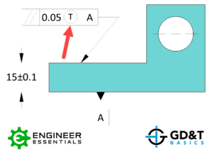
Symbol: Ⓣ
Definition:
The Tangent Plane Symbol is used in conjunction with Geometric Dimensioning and Tolerancing surface controls to indicate that a specific control is applied to a theoretical tangent plane simulated by the high points of an irregular tangible surface rather than the actual elements of the surface themselves.

Applying the Tangent Plane Symbol:
The Tangent Plane Symbol is applied after the stated value for the tolerance in the Feature Control Frame as seen above. The symbol can be used for any surface controls such as Perpendicularity, Parallelism, Angularity, or any other GD&T symbols where the surface is related to datums.

When the Tangent Plane Symbol is utilized on a feature the surface elements are no longer being controlled by the tolerance zone – only the Tangent Plane must remain within the stated tolerance. The tolerance zone is not affected by the symbol and is to be analyzed as it normally would be, for this example the tolerance zone remains parallel to Datum A and consists of two parallel planes spaced .05 apart. One side effect to using the Tangent Plane Symbol is that the symbol will no longer control flatness, only orientation. If flatness is desired to be controlled, it will need to be controlled separately.
Be The Go-To Engineer at Your Company
Learn GD&T at your own pace and apply it with confidence in the real world.
GET GD&T TRAINING


