
GD&T Symbol: 
Relative to Datum: No
MMC or LMC applicable: No
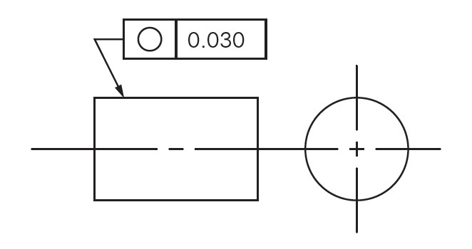
Drawing Callout:
Description:
The circularity symbol is used to describe how close an object should be to a true circle. Sometimes called roundness, circularity is a 2-Dimensional tolerance that controls the overall form of a circle ensuring it is not too oblong, square, or out of round. Roundness is independent of any datum feature and only is always less than the diameter dimensional tolerance of the part. Circularity essentially makes a cross-section of a cylindrical or round feature and determines if the circle formed in that cross-section is round.
GD&T Tolerance Zone:
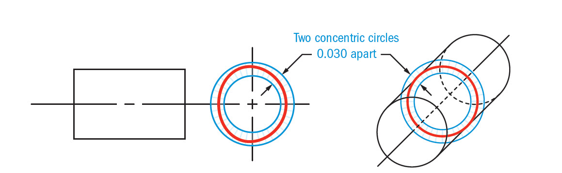
Two concentric circles, one inner and one outer, in which all the points within the circular surface must fall into. The tolerance zone lies on a plane that is perpendicular to the central axis of the circular feature.
Gauging / Measurement:
Circularity is measured by constraining a part, rotating it around the central axis while a height gauge records the variation of the surface. The height gauge must have total variation less than the tolerance amount.
Relation to Other GD&T Symbols:
Circularity is the 2D version of cylindricity. While cylindricity ensures all the points on a cylinder fall into a tolerance, circularity only is concerned with individual measurements around the surface in one circle. If you think of a stack of coins, circularity would be a measurement around one coin while cylindricity would have to measure the entire stack. (cylindricity is actually a combination of circularity and straightness)
When Used:
Circularity is a very common measurement and is uses in all forms of manufacturing. Any time a part needs to be perfectly round such as a rotating shaft, or a bearing, circularity is usually called out. You will see this GD&T symbol very often on mechanical engineering drawings.
Example:
If you had a hole that was around a rotating shaft, Both pieces should be circular and have a tight tolerance. Without circularity, the diameter of the hole and shaft would have to be very tight and more expensive to make.
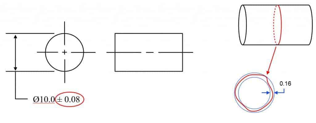
Example 1: Controlling circularity without GD&T Symbol
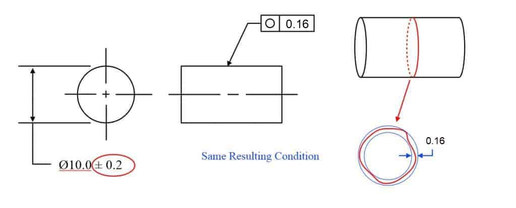
Example 2: Controlling both features with circularity allows the diameter tolerances of the part to be opened up much larger.
Why isn’t the circularity 0.08 to replace ±0.08 of size tolerance?
You may be thinking, “well hang on – if it is ± 0.08 and circularity is the radial distance between the two circles, wouldn’t that mean the circularity should be only 0.08 since it would be on both sides? No – and this is because of how the two-point measurement of any feature would work when compared to the smallest size vs the biggest size it could be. In Geometric Dimensioning and Tolerancing there is a rule that states you need perfect form at the MMC size – meaning at the largest size for a pin (smallest for a hole), your shape of this round feature cannot let it outside of a size of 10.08 for the first example.
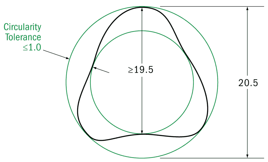
Here is a diagram showing where the surface is allowed to lie without any circularity added for a size tolerance of 20±0.5. As you can see the max size can cause the shape of the part to go to 20.5 – just like you would assume. However due to the rule in the GD&T standard – the LMC size – in this case, the smallest size tolerance, only needs to be inspected with a two-point measurement. For an odd-number lobed part – geometrically this means that the circularity is limited by the TOTAL size tolerance. So for a size tolerance of 1.0 (±0.5), your equivalent circularity control would be 1.0.
We go into depth on this in our GD&T Fundamentals Course when we talk about Rule #1 – the Envelope Principle and how it needs to be inspected.
To Recap – you need to be within a perfect boundary at MMC (largest pin, smallest hole) but for the LMC (smallest pin, largest hole size) you only need to take a 2-point measurement.
Final Notes:
Roundness:
Circularity in Geometric Dimensioning and Tolerancing is sometimes also referred to as Roundness. Since it is a 2-Dimensional tolerance sometimes multiple sections of the same feature must be measured to ensure that the entire length of a feature is within roundness. Usually, two or three measurements are taken to ensure the part meets roundness for each segment of the part.
Statistical Tolerance Stacks:
Because circularity specifies the form of the surface in a specific area it needs to be considered when calculating a statistical tolerance stack. For example, if you have a part with a specified diameter and circularity callout, you must use both in your statistical stack since the geometric tolerance can contribute to a large part envelope than just the diameter tolerance alone. This will skew the statistical tolerance slightly higher and should be considered since parts are rarely perfectly circular.
Be The Go-To Engineer at Your Company
Learn GD&T at your own pace and apply it with confidence in the real world.
Get GD&T TrainingAll Symbols


I’m having question about circularity, for example if the dimension is diameter 6 +0.012/+0.004. How can I define proper circularity.
Miha –
Circularity is a profile control. This means that only surface elements of the feature are actually being controlled. The tolerance zone for circularity is two concentric circles, the distance between is equal to the value in the feature control frame. As with all form controls, you get an indirect control from the limits of size. In your case the possible circularity error is .016. Theoretically this means that an individual slice of you pin/rod could be offset from an identical element directly below by as much as .016. Likewise, your circular element could be ‘squashed’ into more of an oval shape by the same amount. If you’re not as concerned as much about size but wish to retain a circular shape, then a circularity control is what you want. Note that to have any meaning then, your circularity control must have a tolerance <.016. Lastly, you should also note that circularity can not control taper or straightness. For that you need to use cylindricity. I hope this helps your understanding of the issue. Please keep coming back for more helpful tips and I'd encourage you to take use of our courses available at GD&T Basics! Cheers, Matt
Hi,
I found a Roundness in a drawing with tolerance +0.5/-0.7 on the Feature control frame. I don´t know how is the interpretation. Exist some standar ISO, ASME, etc. to explain this?
Thanks.
Mario –
Do you mean circularity? Roundness isn’t a control per ASME Y14.5. Also, there can’t be a variable tolerance in the feature control frame. The tolerance has to be a single value. Is it possible the +0.5/-0.7 is the size tolerance for the part?
The tolerance zone for a circularity control is two concentric circles that are radially spaced apart by the amount specified in the feature control frame. There is no size associated with the tolerance zone. The requirement is that the entirety of the surface of the part has to exist in the zone between the two circles or the part is rejected.
I hope this helps your understanding. If I’ve misunderstood or mis-stated something please come back and try again.
Cheers,
Matt
For the first example, it says +/- .08, shouldn’t the circularity be 0.16?
The LMC – smallest size is a two-point measurement – not a diameter. On a tri-lobed part – the MMC would be the smallest perfect circle that can fit around the entire shape. The LMC would the worst case two-point measurement. See this image in the note at the bottom of the page for details on this. https://www.gdandtbasics.com/circularity
I got a question about circularity which makes me so confused. If the customers require circularity 0.2 for the bar/rod, what the tolerance I should put on diameter? +/- 0.1 or +/-0.2 ?? One of my engineers said circularity should be calculated the difference of the radius, so it should be +/- 0.2 for the tolerance of diameter. Another one said it should be calculated the calculated from diameters, so the tolerance of diameter should be +/- 0.1.
I would appreciate if someone could teach me which one is correct.
Thanks
Sean
We have a customer who specified OD (of a pipe) to be x +/- 0.03″
They had no callout for roundness, hence our Production techs used pi-tape to measure diameter.
Customer subsequently rejected parts as some measurements, diameter was outside of the tolerance.
I suggested they add a roundness callout. Now they are asking me to suggest the tolerance for roundness.
My initial thought was 0.03″, however, after looking for more information to confirm my initial thought, I am now thinking wiser to post the question here.
I did get that the roundness tolerance must not be greater than the diameter tolerance (or it would have no meaning), but perhaps it is not necessarily wise to have it equal – maybe it should be less.
The pipe is being inserted into a hole on a mating machined plate and welded in place. Any suggestions on the roundness tolerance? Thanks,
James –
You’ve hit on one of the main themes of GD&T. Your statement about having a geometric tolerance smaller than the size tolerance is due directly to Rule #1, which states that you must have perfect form at maximum material condition. A circularity control is a form control and your size tolerance includes an inherent circularity control. Per the rules of GD&T, if your pipe was produced at the maximum limit of the size tolerance it would have to be perfectly circular. It is only as the pipe departs from this maximum material condition towards the least material condition that you are permitted any circularity error. In your particular example you have a total tolerance of .06 (from the x +/- .03), this means you have two concentric circles one of diameter x+.03 and one of x-.03. The radial distance, or gap, between the two circles is .06 and your maximum form error could be as high as .06 if you didn’t add any additional requirement onto the print.
Your initial thought at a circularity tolerance wasn’t a bad start, but it should be obvious now why your geometric tolerance for form controls must always be smaller than your total size tolerance.
I hope this helps.
Cheers,
Matt
If I have a feature that has a diameter tolerance of +/- 0.4 and a circularity tolerance of 1, is the circularity requirement performing no function? With the circularity being larger than the feature tolerance, doesn’t that create a conflict in the definition?
Rob –
You are 100% correct. Since circularity is a form control it is a requirement that the tolerance for circularity be smaller than the size tolerance. The geometric control you are describing has no meaning since by default you are controlling circularity through the limits of size.
I hope this helps.
Cheers,
Matt
“Roundness is independent of any datum feature and only is always less than the diameter dimensional tolerance of the part.”
Does this mean that the circularity tolerance lives INSIDE the tolerance of the diameter, and is not additive? Just looking for clarification there.
Yes, James… that is correct. (There is one exception: when you use an average diameter callout for a part such as an O-ring. But an avg is not really the true diameter anyway.) So according to the ASME standard, the diameter callout on the part must encompass circularity, since circularity is merely a form control.
For this reason, I think there is a small goof in the article above. In the paragraph about “Statistical Tolerance Stacks,” it says that “if you have a part with a specified diameter and circularity callout, you must use both in your statistical stack since the…geometric tolerance can contribute to a large part envelope than just the diameter tolerance alone.”
That’s not really true 🙂
Hello,
I have a question regarding a drawing symbol. However I need to show the drawing here in order to ask my question. Please guide me as to how I can upload the snapshot of the drawing.
Thanks in advance,
Shirish Gupta
Shirish –
Feel free to email me at . I’ll gladly help you out.
Cheers,
Matt
i am making hole with dia9mm with H8 tolerance.
what should be the circularity tolerance for this hole.
Hemant –
Ok, full disclosure here. You are talking about the ISO standard which isn’t something we specialize in. Our focus is almost exclusively to the ASME Y14.5 – 1994/2009 standard.
A little research shows that for an H8 tolerance and a 9mm hole results in +0/-0.022. The limits of size (9 and 8.978) form the two extremes of your part. Per Rule 1 you have to have perfect form at MMC. In this case MMC is equal to 8.978 and your form (circularity) is only able to vary an amount equal to the amount of departure from MMC. Thus, in order to have any effect on the circularity, you would need to have a circularity tolerance tighter than 0.022.
How tight does your tolerance need to be? I really can’t answer that, it really depends on what you are trying to do with it.
I hope this helps.
Cheers,
Matt
Hi,
First of all sorry for deviating the topics of discussion from circularity to controlled radius.
I have read about the controlled radius, it defines that radius arc should be without flat and reversal. But I am really interested to know, how is it possible to manufacture radial arc without flats and reversals. No matter how precise its manufacturing process is, there will always be flats and reversals to some extent.
Please also mention the significance of controlled radius and its application? why and where it is used?
Thanks in advance
Sandeep –
I’m not sure I can be of much help in regards to this question, but I’ll try. Personally, I have never had cause to use a controlled radius in any of my designs. As far as why you might need them is application specific. Perhaps you have something sliding or moving and want to reduce friction as much as possible. Another application might be in a pressure regulator where rough radii cause turbulent flow resulting in a ‘water’ hammer effect that adversely affects your flow. As for how this is done I’m not sure, I’m not a machinist. I suspect that the true intent here is that the tool path must be continuous without pause or backing up, but I’m not positive.
Hope this helps. Let us know how else we can help you further understand GD&T.
Cheers,
Matt
Hi,
I have a situation where on shaft, there is a requirement of parallelism of 0,033mm on shaft dia. upper face wrt shaft diameter lower face and roundness of 0,014mm. Supplier is asking for deviation as parallelism of 0,1 mm and roundness of 0,1mm.
Is it possible that both parallelism and roundness can have same value? I have an idea that roundness is the refinement of parallell surface when both tol. are specified on same diameter.
Is there any relation between of parallelism and roundness ?
I have mostly seen that roundness is almost half of parallelism.
Roundness and parallelism are typically independent as parallelism controls orientation axially, and roundness controls the radial form of the part. So yes you can have them completely independent of each other. They control two different portions of the part. This is common with bearings to avoid using the tought to control/measure cylindricity tolerance.
How to Measure Circularity Manually?
Ganesh –
Metrology isn’t my strong suit. Without knowing what you’re trying to measure and what tools you have on hand, or whether you have any kind of budget to procure additional tools it’s difficult to give you direction. You might read up at this page to see if you can’t find a method that works for your application:
http://what-when-how.com/metrology/measurement-of-circularity-metrology/
Cheers,
Matt
that’s not completely true. First example limits are 9.92-10.08 whereas the second example limits are 9.8-10.2.
The difference between the maximum and minimum OD is the same.
This is simply to show that using circularity will allow the same resultant geometric condition, while allowing for the tolerance of the OD to be opened up a bit.
You are right. It will be the same geometric condition but not the same dimensions.
Thank you so much. I was losing my mind trying to figure out how the same functional dimensions resulted from the two approaches. I think this could be more clear in the text.
what is the method measuring roundness using smart scope? any one has idea?
How are the dimensions with/without gdt same?
With Circularity, you no longer need to tightly control the diameter resulting in the same circular condition. If you were not to use Circularity you would need to tighten the diameter.
Great website! I had a question about one of your figures. The first figure in the example you give a diameter of 10 +/- 0.04, but then show the circularity as 0.08. In this case, shouldn’t the circularity be 0.04 since your are specifying diameter and not radius? The way I understand it is that circularity is basically the variation in the radius, and when the diameter is 10 +/- 0.04, the radius is varying by 0.04. If the radius was specified as 5 +/- 0.04, then I could understand the circularity being specified as 0.08. I hope that makes sense. Thanks!
You are right! sorry for the typo, we had originally labeled it a radius and then changed it to show a dowel diameter. The theoretical concentric circles that rule# 1 of GD&T would control would be 9.96 and 10.04. Although these are 0.08 different, the concentric circles would only be 0.04 apart. Good eye and thanks for the heads up!
I thank you in advance and wishing more success for you .
yours faithfully
Thanks for the feedback! I’m glad we can help!
Could you provide some example how people measure circularity(roundness).
Circularity is usually measured with a CMM and a rotating fixture. The CMM is able to Map out the the surface while eliminating the effect of the fixture. There is no datum for circularity so you cannot simply measure with a height gauge. Simply holding a part and rotating it would result in a runout control instead of circularity. You must have some kind of software or computer measurement to get an accurate calculation of circularity.
A CMM is not generally a good tool for measuring form type dimensions. It can be used, but you must be very aware of lobing effects from the force module. Many units such as a TP2 use an internal 3 point contact system that can cause errors in form measurements. But there are units such as the TP200 that use a strain gage technology and eliminate this effect. Just be aware.
I agree to an extent – Measuring instruments are only as good as those who use them. I would take a well experienced tech using dial indicator and adjustable gauge pins over a newly trained person with a CMM any day. It all depends on the number of points you take and your setup. Circularity and Cylindricity are tricky ones, as you really need to get a significant number of points to truly tell if the form is met.
The Renishaw strain gauge probes are certainly more advanced that simple touch probes and would probably provide a more accurate measurement. However the CMM software would still be operated properly to still achieve the correct results.
Great comment – Thanks!
In my view, CMM isn’t the right instrument to measure Circularity() unless you have a high end CMM which costs fortune.
2 Main reasons why CMM isn’t the right instrument.
1. Part remains constant and probe moves along 2 axis. (Inaccurate)
2. Alignment: In CMM part will be aligned theoretically but not physically.
When form tester/Roundness testers are used both the above points will be eliminated as the part will be rotating and probe remains constant.(Very accurate type of measurement.) and part can be aligned physically.
Anyhow the selection of instrument always depends on the Toll specified.
awaiting your view on my comment.
I frequently need out of round specs on Engine Cylinder bores. these are normally measured just below the top Piston Ring. Wearlimits (in % of the Diameter) would help me a lot
Yeah – circularity is used A TON in automotive. I worked in transmission design and it was rare to find any drawing without the circularity callout all over it. If you are looking for something to help with wear limits you may want to look at adding a PMR (primary material ratio) callout to your print. This is outside of the realm of GD&T but basically controls your form and roughness ensuring your contact ratio is maintained.