

 The Cylindricity symbol is used to describe how close an object conforms to a true cylinder. Cylindricity is a 3-Dimensional tolerance that controls the overall form of a cylindrical feature, both ensuring that it is round enough and straight enough along its axis.
Cylindricity Symbol and Callout
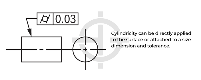
Cylindricity is independent of any datum feature, meaning it will never control the location of a feature with respect to any datums. Cylindricity can only be applied to cylindrical features both internally as well as externally. The symbol will ensure the overall form of a cylinder is not bowed or tapered down the axis of the feature. It also controls the cross sectional shape or circularity of the cylinder. This tolerance controls all surface elements that make up the cylinder. The feature control frame can be attached directly to the feature or also attached to the size dimension and tolerance that is associated with the feature when applicable.
Cylindricity Tolerance Zone
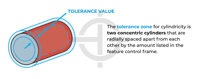
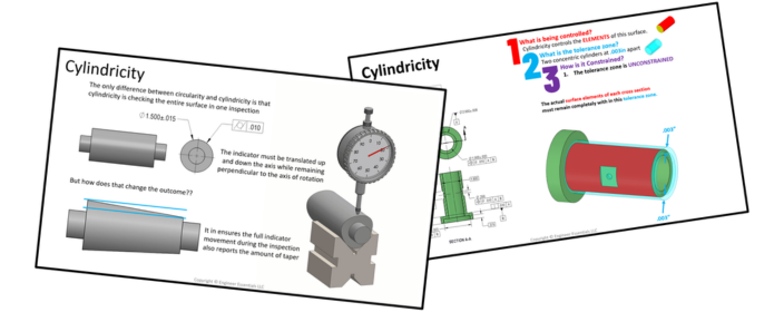
The tolerance zone has two concentric cylinders, one inner and one outer, that run the entire length of the feature. To pass this tolerance requirement, all the surface elements must be able to simultaneously fall within the zone. The tolerance zone is free to move and rotate relative to other features. The value of the feature control frame for the cylindricity tolerance is the radial distance between the two concentric cylinders that establish the tolerance zone.
How to Inspect Cylindricity
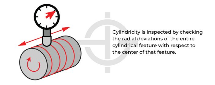
Cylindricity is measured by constraining a part on its axis and rotating it around while an indicator records the variation of the entire surface during one single measurement. The indicator must have total variation less than the tolerance amount. Note that the rotation must NOT be created from any datum features but rather from the specific feature where the cylindricity control is applied. Due to the difficult nature of using the feature to establish rotation AND inspecting the feature at the same time, it’s best to consider, for critical situations with tight tolerances, inspecting cylindricity with a roundness checker or runout checking machines.
Cylindricity Considerations
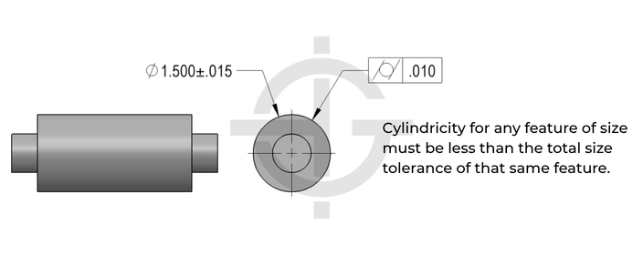
You may not realize it, but just like circularity, your size tolerances already control cylindricity. This is because Rule #1 will ensure the form of the feature does not deviate beyond an envelope of perfect form at MMC. We go into depth on this in our GD&T Fundamentals Course when we talk about Rule #1 – the Envelope Principle and how it needs to be inspected.
We cover the intricacies of cylindricity, how it’s interpreted, how it’s inspected, and the miscellaneous things you should know about this symbol in our GD&T Fundamentals Course as well as our GD&T Inspection Course. These courses show you everything you need to know about cylindricity and then some!
Example and When to Use Cylindricity
Cylindricity is a fairly common callout for shafts, pins and any critical cylindrical element. When a part needs to be both round and straight along its axis, such as a sliding shaft or a dynamic locating pin, cylindricity is usually called out. You will see this GD&T symbol very often in automotive drawings and mechanical systems.
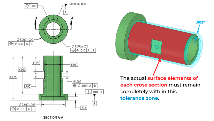
For example, if you had a bushing that was to be pressed onto a shaft like the example above, the bushing would take the form of the shaft when applied. To ensure that the bushing maintains its round shape, and wears evenly along its surface, the shaft cylinder needs to be very cylindrical. To do this without Geometric Dimensioning and Tolerancing you would need very tight dimensions on the diameter of the bore, which may be very hard to control when being machined (and expensive). This GD&T control allows the diameter tolerances of the part to be opened up larger. You can now accept a much broader range of hole sizes as long as the cylindricity is met.
Additionally, when location of the feature is necessary, total runout will already control the cylindricity of a feature but adds the additional control of location with respect to an axis. Cylindricity will not be able to control location. In those instances you can still refine the cylindricity of the feature to a tighter tolerance if necessary.
Cylindricity vs. Circularity
Cylindricity is a merger of circularity and surface straightness. It is the 3-Dimensional version of circularity along an entire cylinder length. While circularity only is concerned with individual measurements around the surface in one circle, cylindricity takes into account how straight the axial portion of the cylinder is. Thinking of stack of coins, cylindricity would measure to make sure that the entire stack is straight up and that every coin is round. Circularity would only be measurements of the roundness of the individual coins. One additional consideration is that cylindricity WILL control the amount of taper to its tolerance value, while circularity WILL NOT.

All Symbols



































Hello team, Can you please explain if material modifier can be used with cylindricity and why?
Hi Lokesh –
Cylindricity is a form tolerance and it is NOT eligible to use either the LMC or MMC modifier. The tolerance zone for cylindricity is two coaxial cylinders spaced apart an amount equal to the value in the tolerance block of the feature control frame. The entirety of your surface, a pin for example, must reside within the tolerance zone to be considered acceptable. The only form controls that have an ability to use the MMC or LMC control are straightness and flatness as they have the ability to control the axis or the derived median plane respectively. Circularity and cylindricity are strictly surface controls.
I hope this helps clarify your understanding of the situation. Keep coming back for more and I hope you take advantage of some of the great courses we have available at GD&T Basics!
Cheers,
Matt
Can I use cylindricity toleance on an edge round? I’d guess not based on previous answers. What ff I want to ensure straightness and roundness along the length of e.g. a 90 degree round on the edge of a sliding part?
yes this is acceptable, but more commonly done with surface profile.
Hi,
You have used straightness symbol and cylindricity symbol for the same round ( in your explanation), in the both cases we will get the same result. Am I Right can you explain it please
Straightness is the form along the axial direction, while circularity is the form radially around the part. both can be independent of each other though.
With cylindricity you cant use MMC or LMC!
if a bush diameter 30 mm and using H7 tolerance . How can i apply cylindricity on that???
Why do some cylindricity tolerances has dimension limits? For example a shaft with diameter of 1.000 +or- 0.002 has a cylindricity tolerance of 0.004mm. What is the virtual diameter of this? Thank you
Why do some cylindricity tolerances has dimension limits? For example a shaft with diameter of 2.798-3.000 mm has a cylindricity tolerance of 0.1mm. What is the virtual diameter of this? Thank you
How straightness has the possibility to over ride rule 1? . (I heard that straightness to FOS results in virtual boundary condition which instate cannot be violated because of Mmc boundary cannot be violated.) couldn’t understand it!
I don’t know the difference between ovality and circularity? It’s both word are similar word or not? Also symbol both are same or not?
Naresh –
Not completely sure what you are referring to. Ovality is not a listed GD&T control per ASME Y14.5 or the ISO standard. Can you provide additional clarification for your question?
Cheers,
Matt
Hello,
This article seems very good.
I had one doubt on designing a plug gauge which will work as a go gauge. Hole has a dimension of 30(0 to +0.021).
It has got cylindricity of 0.02 and concentricity of 0.03. Can you suggest what should be the OD of pin gauge considering taylor’s gauging principle? Should I consider cylindricity and concentricity in MMC calculation? If not, how should I approach?
Thank you,
Nayan
Due to the taylor’s/envelope principle your size cannot ever exceed your form meaning the largest envelope it could be would be is always the size tolerance. This is assuming you are using the ASME standard or the ISO standard with the Envelope rule (E with a circle around it) in your print. The cylindricity tolerance seems a bit redundant since the size tolerance would already control your cylindricity to 0.021. Hwoever if the toylor principle is not applied (it is not default in the ISO standards) then your part could grow beyond that envelope to a theoretical 30.041 range. The concentricity does not limit the extent of your form (it is essentially just a location requirement that controls even distribution of mass), so it does not play into the form envelope of your controlled by the taylor principle on the part.
Hi,
If you have a diameter dimension and attached to it composite feature control frames of 2 tires 1st for “Position” and the 2nd for “Concentricity”
Can you add a 3rd tire having the “Cylindricity” symbol? or it shouldn’t be attached to a dimension?
Thanks
I do not see in the standard, where this is an incorrect way to control a feature of size. Therefore I default to the “would this make sense handing it to someone who doesn’t know what I am specifying” check. I don’t see a way to misinterpret what you are doing so I would say that this is okay.
Hi,
this is one subject that is evoking a lot of discussion in my company. The problem we have is we have drawing offices located around the world. Some apply the rules of ASMI (envelope rule 1) but others in Europe design to ISO rules (BS8888) The parts however can be manufactured in both US and European sites but the drawings do not stipulate the Standard they have been designed to so manufacturing are not sure of the design intent.
This becomes a real big issue because the parts we manufacture (sleeves to fit over customer shaft (h6)) have to be very tightly controlled for size i.e. F7 so if we apply the rules od ASME this mean the roundness (circularity) is controlled by the size i.e. 50mm would mean a roundness control of 0.0125. If we apply the rules of independency as per the ISO rules this is no longer the constraint so my question is can the roundness be greater than the diameter size tolerance?
Paul –
First things first. It is imperative that your drawings state somewhere on them what standard is being used to dimension them. Otherwise, how is the machine shop to know what set of rules to follow? My company has this information stated within the title block as an example.
As for your specific question, no, the tolerance for roundness can not be greater than the diameter size tolerance. This is the case with all form tolerances unless the independency symbol is called out next to the control or there is a note somewhere on the drawing that leads back to the control along the lines of ‘Perfect Form at MMC not Required’. The other exceptions to this rule are for straightness and flatness applied to feature of size at MMC.
I hope this helps.
Cheers,
Matt
very helpfull thanks.
Hallo, in the Cylindricity example 1: Controlling cylindricity without GD&T Symbol, you put Φ10.0±0.04 that imply a cilindricity of 0.08, but the radial distance between the maximum and minimum size of the cylinders is 0.04 in radial direction. (Max Radius = 5.02; Min Radius = 4.98) ∆Radius = 0.04 = Cilindricity tolerance implied. Am I wrong?
Best regards and compliments for your site.
Paolo –
This can be a little confusing so hang with me. Without a cylindricity control you are relying on size to control cylindricity for you. Recall Rule #1, perfect form at MMC. As your part departs from MMC your part is allowed a form error equal to the amount of departure.
Keeping with our example. The tolerance zone for cylindricity is two co-axial cylinders. As long as all portions of the surface of the cylinder are within this zone the part is good. Well, what are the sizes of these two co-axial cylinders? Remember, we’re dealing with form here not location. The larger cylinder is easy to define, it’s equal to 10.04. The smaller cylinder tolerance zone has a diameter of 9.88. Now, what is the smallest cylinder that fits between the co-axial cylindrical tolerance zones while meeting the size tolerance requirement? The answer is 9.96 which happens to be 10 – 0.04!
How does this work? Recall that I said that location was not being controlled? The part is allowed to ‘float’ within the zone defined by the two co-axial cylinders. There are 3 stipulations: 1 – The part must remain within its size tolerance. 2 – No element of the part may cross over the zone defined by the larger cylinder. 3 – No element of the part may cross into the zone determined by the smaller cylinder.
Draw on a piece of paper two concentric circles. The inner circle has a radius of 4.94 and the outer circle has a radius of 5.02. Now, draw a third circle such that the left edge is at -4.94 on the x-axis and the right edge is at 5.02 on the x-axis (the center of the 3rd circle must be on the x-axis). The diameter of this third circle? 9.96, the LMC limit of your part.
I hope this clears things up. Best of luck.
Cheers,
Matt
Hi Matt,
I managed to wrap my head around the points you raised in this comment and felt it made a lost of sense and that I had a good understanding of why the cylindricity for the first part of the example is 0.08. However, I don’t see how the tolerance of the diameter can be relaxed and still give the same result. I’ve broken down my thoughts in to five parts:
(1) My understanding is that without GD&T the cylinder is controlled by the diameter, Ø10±0.04, so can vary between 9.96 & 10.04.
(2) My understanding is that a cylindricity of 0.08 introduces two co-axial cylinders with a difference of 0.08 units on radius.
(3) My understanding is that a larger co-axial cylinder of Ø10.20 and a smaller co-axial cylinder of Ø10.04 would satisfy both the diameter & cylidricity tolerance specified in part two of your example.
(4) Similarly, a smaller co-axial cylinder of Ø9.80 and a larger co-axial cylinder of Ø9.96 would also satisfy both conditions in part two of your example.
(5) My understanding is the cases put forward in (3) & (4) could not happen simultaneously as this would then violate your cylindricity but I don’t understand how either co-axial cylinder is defined when the diameter tolerance is larger than the cylindricity.
On-top of this neither cases put forward in (3) or (4) are equivalent to (1). Can you please identify any misinterpretations I’ve made? I find the concept of cylindricity easy to think about as long as the diameter is more tightly controlled than the cylindricity.
This is very helpful, THANK YOU!!
Can you apply cyclindricity to a drafted cylinder? If not what would you suggest for a situation such as this?
Cylindricity only controls perfect cylindrical shapes. It all depends on what you are controlling. You could use straightness and circularity together to maintain a straight & round taper. Essentially this would be cylindricity without needing to ensure the two opposing sides are parallel.
Hi, I really appreciate your explanation. One aspect of GD&T that always confuses me is the relationship of Rule 1 to other tolerances. In your “example 1” above, if the red cylinder is the MMC of Ø10.4 and the blue cylinder is the LMC of Ø9.6, should the radial dimension as shown be 0.04? I’ve always assumed the “implied cylindricity” according to “Rule 1” was one half of the tolerance band. By my assumptions, a feature with dimension Ø10±0.04 has a total tolerance band of 0.08 and an implied cylindricity within 0.04.
Where am i going wrong?
This is a concept that boggled my mind when I first thought about it. It should be half right? Well the limits of size for Rule #1 define that no part of the surface can exceed the perfect boundary at MMC. However, the minimum is the smallest 2-point measurement across the diameter & has to be larger than LMC. So for circular parts, yes the Cylindricity would be about half of the size tolerance. However what about a lobed part with 3 lobes? Check out the sketch below. 20.5 is the max size and 19.5 is the min size of the part.
If you are interested, we discuss these common issues and everything else in our GD&T Basics Training Course – Be sure to check out our training page if you or anyone at your company is interested in having the ultimate online GD&T resource. We make sure that we break down everything so it is easy to understand.
Great Question!
I found cylindricity symbol with diametre abbreviation in one of my company drw plz explain about
The symbol is like that
Cyl . Symbol/ dia symbol 0.004
Cylindricity should never use the diameter symbol (the tolerance zone is the distance between tow coaxial cylinders.)
If form tolerance is not given, how much we have to take the tolerance, can we take the thumb rule that 1/3 ?
Great explanation but I’m confused about one thing. Say in the last figure you have 10.0 +/-0.2 with a cylindricity tolerance of 0.08. Can the MMC of the cylinder be 10.28 with the cylindricity tolerance?
Thank you in advanced!
Good Question – Actuall due to rule #1 of the ASME standard your form cannot go above the perfect boundary of your MMC. So if your part is 10.2, your form would have to be perfect! We are going to include a lesson on this in the near future.
For cylindricity example 2, wouldn’t an exact resulting condition be: replacing the cylindricity tolerance with a straightness tolerance of .08?
Also, examples 1 and 2 are not the exact same resulting condition, example 2’s cylinder can be much larger or smaller than example 1, but must be .08 smooth surface right? I believe that’s what it’s saying in the description below it.
Cylindricity is how well the part’s form adheres to a perfect cylinder. It takes into account straightness and roundness of the surface already. Example two can only have 0.08 of cylindricity since it is called out, the diameter though can increase in size.
This is very helpful.
Thanks we are glad to help!
Question on variable tolerance; say your OD can have a larger tolerance on the high side, but a lower tolerance on the low side? For example a rolled plate that’s welded to make a pipe. Allowing the manufacturer to error on the high side so that when the pipe is later machined on the OD, the extra material can be removed? How is this shown?
Also, the pipe has to be round, with each point along the surface of the cylinder falling within the same tolerance that is shown on the OD dimension. I have a tolerance on the OD, and want to make sure the cylindricity is taken into account so that no matter where you measure the OD, it is within tolerance. I want to make sure that the manufacturer is not just using a pi tape to measure average diameter.
The good thing about the ASME standard is by default your cylindricity (and all the other form tolerances) need to fall within your size dimensions. So lets say your OD tolerance is 50 ± 0.2. This means your cylindricity is automatically controlled to this limit. Your entire part would theoretically need to fit into a cylinder of 50.2. You could check this with a machined sleeve that ensures the part does not exceed its outer boundary. GD&T can then later refine this in the rolled state. Another addition would be to just use circularity since it is the cross sectional version of cylindricity. Every cross section could to be a different size (your taper from end to end is not controlled), but the part would have to be round.
I want to know the fundamental of the concentricity, cylindric city & circularity.I mean how r they differ from each other?
Sorry, I meant MMC for the question above
When independency is used, you are no longer stating that the size controls your form. So this means your form can allow your part to exceed the envelope. Functional gauging would not work because you would need to independently check the size (diameter) and the form (cylindricity/straightness) to ensure the part function is met. You can no longer simply use a sleeve at MMC to gauge the part.
What if the “Independency Rule” is applicable. Can you make a functional gage at the LMC size the same length of the part, minus the cylindricity tolerance, and simply pass the gage through the part like an attribute gage. Then independently check the I.D. for Size, Roundness and Taper.
very informative
we informative
this was helpful thanx
Great information done in a manner that anyone can understand.
Thanks Dave! We appreciate the kind words. Hope your students find it useful!
Hey, this is a great resource, exactly what i needed 🙂
but 1 thing is unclear for me, how come having cilindricity callout allows for larger tolerances for diameter ?
Cylindricity does not allow necessarily allow your application to have more tolerance on an OD if it will not function at a certain size limit. What it does do though is allow you to ensure that your part is cylindrical without having to tighten the tolerances down crazy tight. Lets say you have a simple roller bearing with needles that need to be cylindrical to wear properly. If you are not as concerned with the height of the bearing (OD of the Needles) but need them to be cylindrical to wear properly, cylindricity can be applied so that your parts form is in spec and held tighter than the actual OD.
Of course, if the application limits of the part require a specific or tighter bearing height (needle OD) then you have no choice but to have a tighter tolerance. GD&T is about function first.
We will be releasing a new section about Rule #1 of the ASME which basically states that your size dimensions also control your form tolerances (straightness, flatness, circularity, cylindricity) within the envelope of the dimensions. Many cases this is enough to control your cylindricity. Cylindricity is a refinement when you really need something cylindrical for function. (its kind of a pain to measure so only use it when you need it!)
can please explain Rule #1 of the ASME ?
Viswanath –
This rule simply stated is: Perfect form at Maximum Material Condition (MMC). It means that within the limits of size, if your part is at MMC there can be no variation in form. It is only as the part departs from MMC towards LMC that form error is permitted in an amount equal to the amount of departure from MMC.
Remember that MMC is defined as the condition that results in the ‘heaviest’ form of your part, i.e., smallest hole diameter, largest pin diameter or block width/length etc.
Hope this helps.
Cheers,
Matt
I like the explanation and samples, well done
Thanks for the positive feedback! We have more content coming soon.