
Special Note:
Straightness actually has two very different functions in Geometric Dimensioning and Tolerancing depending on how it is called out. In its normal form or Surface Straightness, is a tolerance that controls the form of a line somewhere on the surface or the feature. Axis Straightness is a tolerance that controls how much curve is allowed in the part’s axis. This is usually called out with an included call to maximum material condition. Both callouts are very different from each other!
GD&T Symbol: 
Relative to Datum: No
MMC or LMC applicable: Yes – Axis Straightness
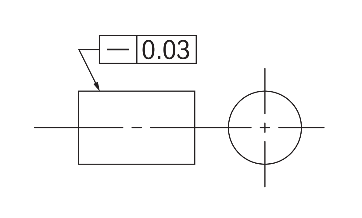
Drawing Callout:
Surface Straightness
Derived Median Line Straightness
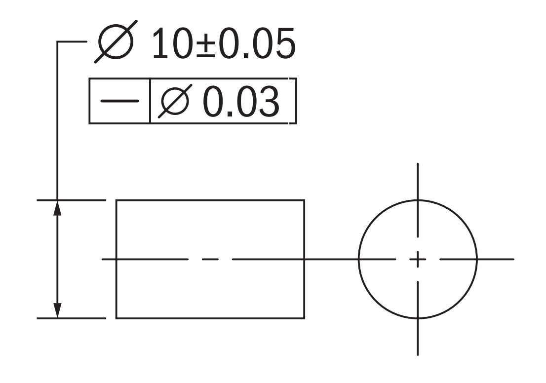
Note: Surface Straightness is called out on the surface of the part. Derived Median Line straightness is called out next to the size dimension of the axis.
Description:
Surface Straightness:
The standard form of straightness is a 2-Dimensional tolerance that is used to ensure that a part is uniform across a surface or feature. Straightness can apply to either a flat feature such as the surface of a block, or it can apply to the surface of a cylinder along the axial direction. It is defined as the variance of the surface within a specified line on that surface.
Derived Median Line Straightness:
The form of straightness that controls the bend of the central axis of a part is referred to as Derived Median Line Straightness. This tolerance callout specifies how straight the axis of a part is (usually a cylinder). By definition, DML straightness is actually a 3D tolerance that constrains the center axis of the part preventing it from bending or twisting too far.
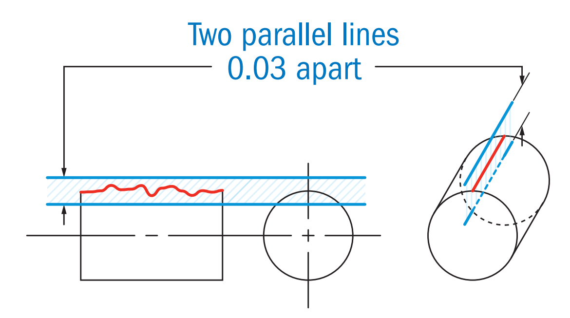
GD&T Tolerance Zone:
Surface:
Two Parallel Lines on either side of a surface line where the surface must lie (2D)
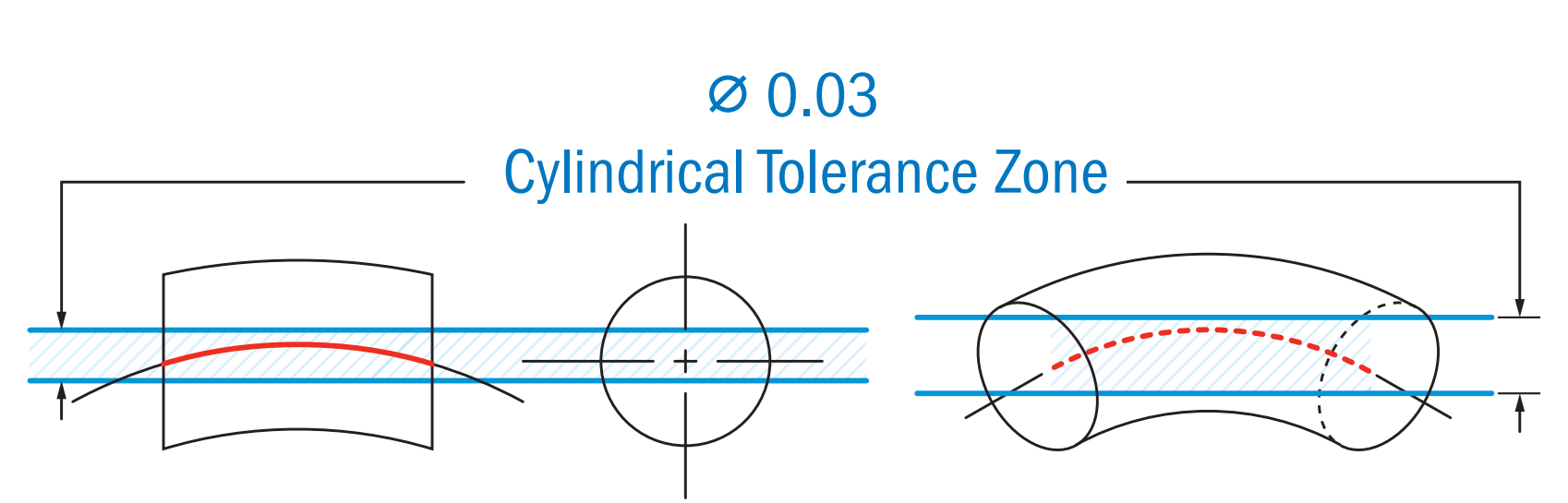
Derived Median Line:
A cylindrical boundary around the true central axis of the part, where the derived median line of the part must fit into.
Gauging / Measurement:
Surface:
A part is constrained and a gage measures along a straight line. In this example, the height variance is measured to see how flat or straight the line is along this surface.
Derived Median Line:
To gage axis straightness effectively, the MMC modifier is sometimes called out on the drawing. To ensure that a part or feature is axially straight, a cylinder gage is used to determine if the part fits in its total envelope at MMC.
This controls the combined effect of the diameter and of the axial straightness. The ID of the cylinder gage represents the maximum virtual condition of the part.
Gage Cylinder ID = Max Ø part (MMC) + Straightness Tolerance
See the 2nd Example below for how axis straightness is used with a maximum material callout.
Note on Bonus Tolerance: When a functional gage is used to measure axis straightness, the straightness tolerance can have bonus tolerance added when the part diameter is smaller than MMC. The goal of a maximum material condition callout is to ensure that when the part is in its worst tolerances, both straightness and dimensionally, that the part will always fit a given size hole. This means that if you make a part smaller in OD, you gain bonus tolerance and can actually have it be less straight! Remember – the goal of this callout is functional: The part must fit in a specific envelope.
Bonus Tolerance = difference between MMC and the actual size of the part.
For more detail, see the sections on Maximum Material Condition.
Relation to Other GD&T Symbols:
Surface:
Straightness can be considered the 2-Dimensional version of Flatness as both are measured without a datum and control and refine the size of the feature. While flatness measures the variance across a 2D plane, Straightness only measures the variance on a straight line.
DML:
Axis Straightness is also closely related to axis parallelism and axis perpendicularity since they both are controlling a center axis with a cylindrical tolerance zone. When MMC is applied, all of these callouts constrain the central axis to a specific variance amount ensuring that even at the worst-case tolerances, the part will function properly.
When Used:
Surface:
Commonly used for sealing surfaces or surfaces that mate with another part. For example, a hydraulic channel cover in a transmission would need to make steel on steel contact in order to seal off the open hydraulic channels and maintain pressure. With a straightness call out you can specify which lines on the surfaces are most critical to making sure the pressure is maintained.
DML / Max Material Condition:
Used mainly on pins or cylindrical surfaces which must be installed with clearance into a bore or hole. The straightness callout ensures that even in the Maximum material condition; the part will still fit its mating hole or section. Straightness is commonly used to control the curve of some parts that may be prone to bending during manufacturing.
Surface Straightness Example:
A steel bar is welded in a T pattern to another steel bar. If you want to make sure that the surface of the tube is always uniform, where the weld occurs, you would need to either greatly tighten the dimensional diameter of the tube, (which would be very costly for such a simple part!), or callout straightness along the mating surface.
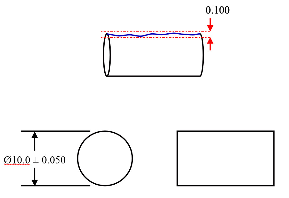
Ensuring straightness without Geometric Dimensioning and Tolerancing
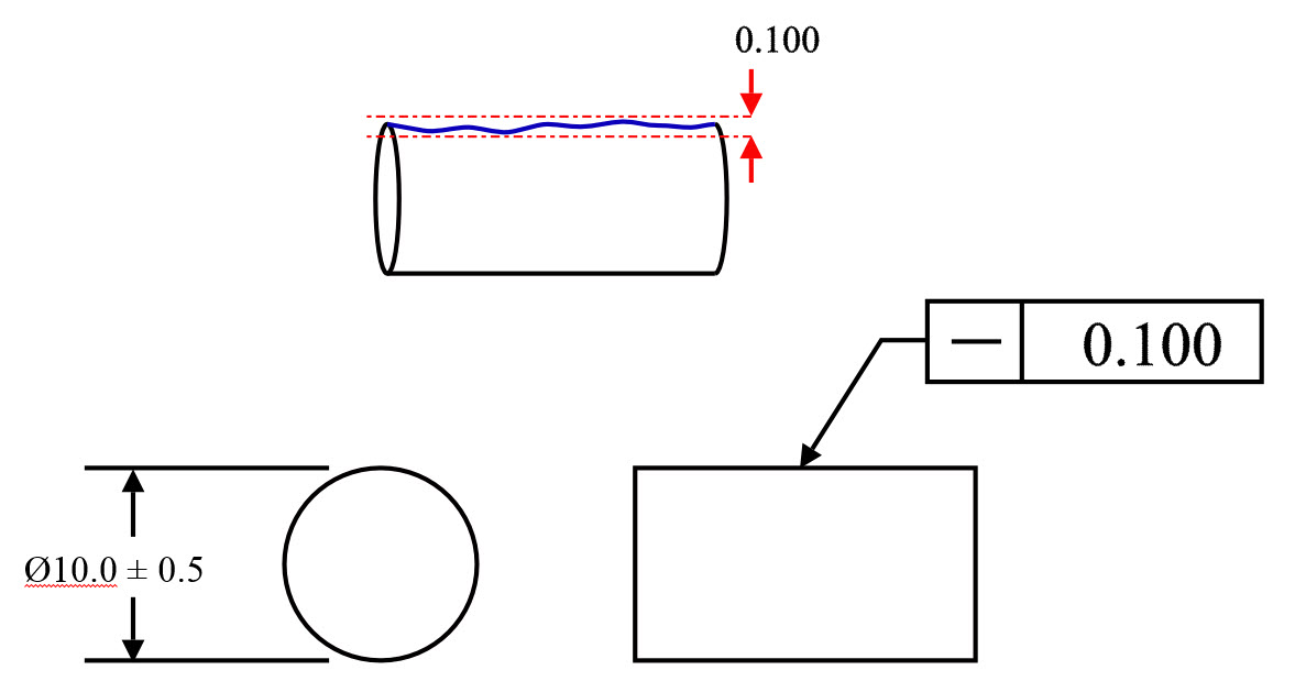
Controlling the surface of the tube in the weld area with GD&T straightness callout.
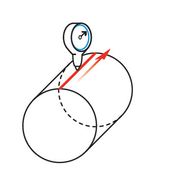
DML Straightness with MMC Example:
A boss pin on an engine housing is inserted into the chassis of a car to set the alignment before being bolted in. The pin is always in the correct position, however since it is so critical the dimension of the chassis mating hole is very tight. To ensure that this pin is always a correct fit for the hole, straightness is called out on the axis with the Maximum Material Condition Modifier.
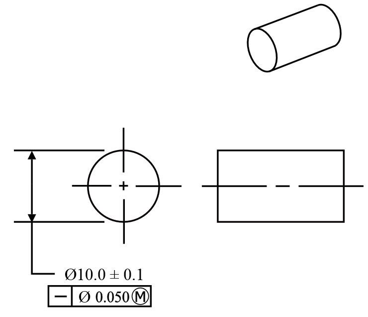
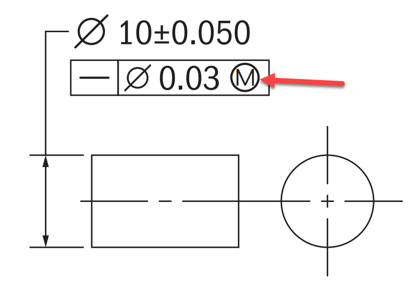
Ensuring straightness on the drawing
To quickly check for this a gage was made to check that the pin always fits into the hole in the maximum material condition. Using the calculation below the ID of the cylinder gage can be determined to check for this during production.
Gage Cylinder ID = MMC + Straightness
Gage ID = Maximum Material Condition of Part + Straightness Bonus Tolerance
Gage ID = 10.100 + .050
Gage ID = 10.150 mm
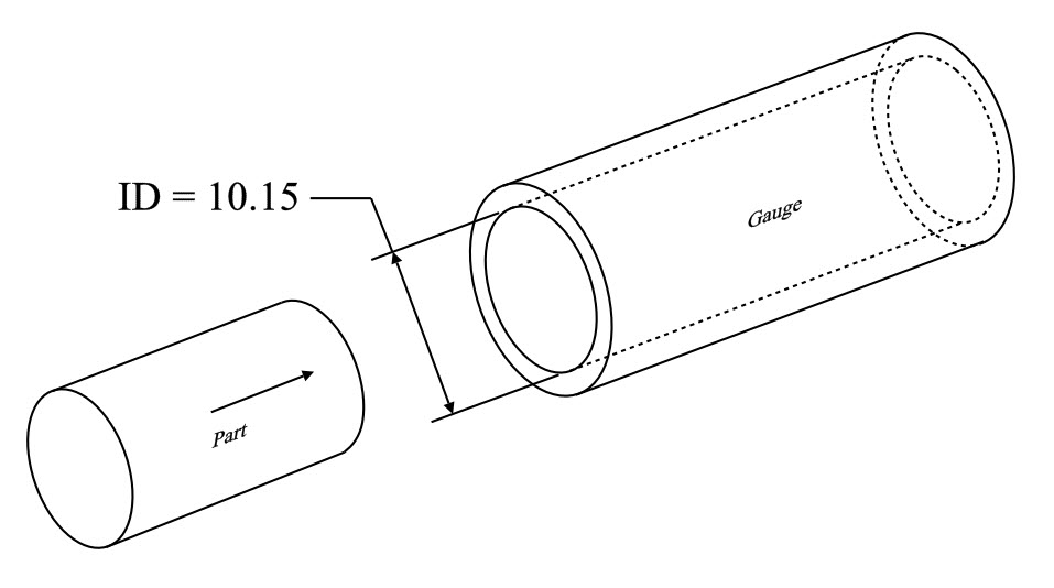
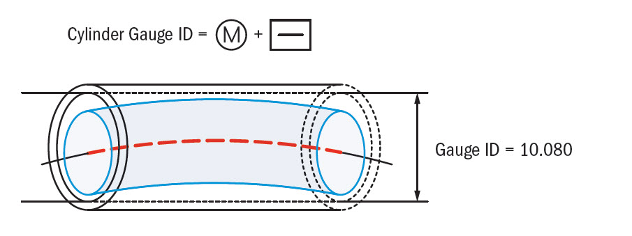
Gage control for axis/MMC straightness
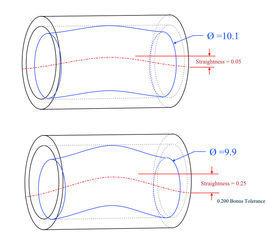
If the part is close to MMC, it has to be a tighter straightness tolerance than if it was smaller and closer to the least material condition. As long as the entire part envelope fits within the 10.15 cylinder, the part is in specification. This extra tolerance on the straightness is the bonus tolerance
Final Notes:
Straightness and Perpendicularity with maximum material condition are most commonly used when controlling the form of a pin – while straightness controls the curve or bend of the center axis, perpendicularity controls the angle at which the pin is to a datum. Both constrain the axis of a pin feature and used gages to control the entire feature’s boundary.
Be The Go-To Engineer at Your Company
Learn GD&T at your own pace and apply it with confidence in the real world.
Get GD&T TrainingAll Symbols


