
Symbol:
Category: Feature of Size
Definition:
Maximum Material Condition or for short, MMC, is a feature of size symbol that describes the condition of a feature or part where the maximum amount of material (volume/size) exists within its dimensional tolerance. The callout also removes GD&T Rule#2 which states that all geometry tolerances are controlled independently of the feature size.
When you have a feature that Geometric Dimensioning and Tolerancing is called on:
If it is a hole or internal feature: MMC = smallest hole size
If it is a pin or external feature: MMC = largest size of the pin
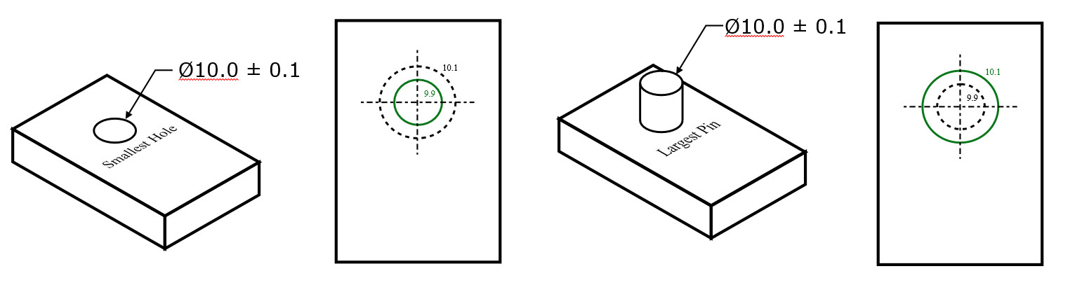
In each of these cases, the part will have the maximum amount of material that would be allowed within the part tolerances.
Max Material Condition is one of the dimensional limits on a part. The other side of the tolerance range would be the Least Material Condition.
The only GD&T Symbols where Max Material Condition can be applied are:
- Straightness (axis)
- Parallelism
- Perpendicularity
- Angularity
- True Position – very common
Reason for Use:
If you want to ensure that two parts never interfere, or limit the amount of interference between the parts when they are at their worst tolerances, MMC can be called out. Take a shaft that must go through a hole with clearance between the two.
The MMC of the shaft would be the Maximum diameter
The MMC of the hole would be its Minimum diameter
If you made sure that the MMC of the shaft was always smaller than the MMC of the hole, you guarantee there will always be clearance between the parts. This is important for any tolerance stack to ensure that when the tolerances are at their least desirable condition, the part still functions properly.
Gauging Max Material Condition:
Maximum material condition comes in handy when it comes to making a functional gauge for the part. If you want to limit the size of your feature, you can specify the max material condition call out additionally control it with Geometric Dimensioning and Tolerancing.
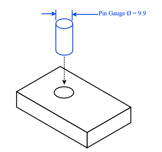
For example if you wanted to ensure that a pin always fits into a hole when the hole is at MMC, we could design a pin gauge that
mimics the lower limit of the hole. The gauge that controls the Max Material Condition of a part is called a Go-Gauge (Meaning the Part must always Go into it)
The Go-Gauge for a hole or internal feature would exist of a pin that is just a tiny bit (few microns) smaller than the Maximum Material Condition of the hole. The gauge pin would then be inserted into the hole and as long as the pin Goes into the hole, the part is in spec.
(Note: The pin gauge may be made slightly smaller (a few microns) than the MMC to account for any straightness or tolerance issues that may be inherent in producing the gauge)
*Remember when no GD&T is called on the hole the envelope principal applies – meaning the geometric and size effects of the hole cannot be larger or smaller than the tolerances specified.
Combination Gauging with GD&T Symbols
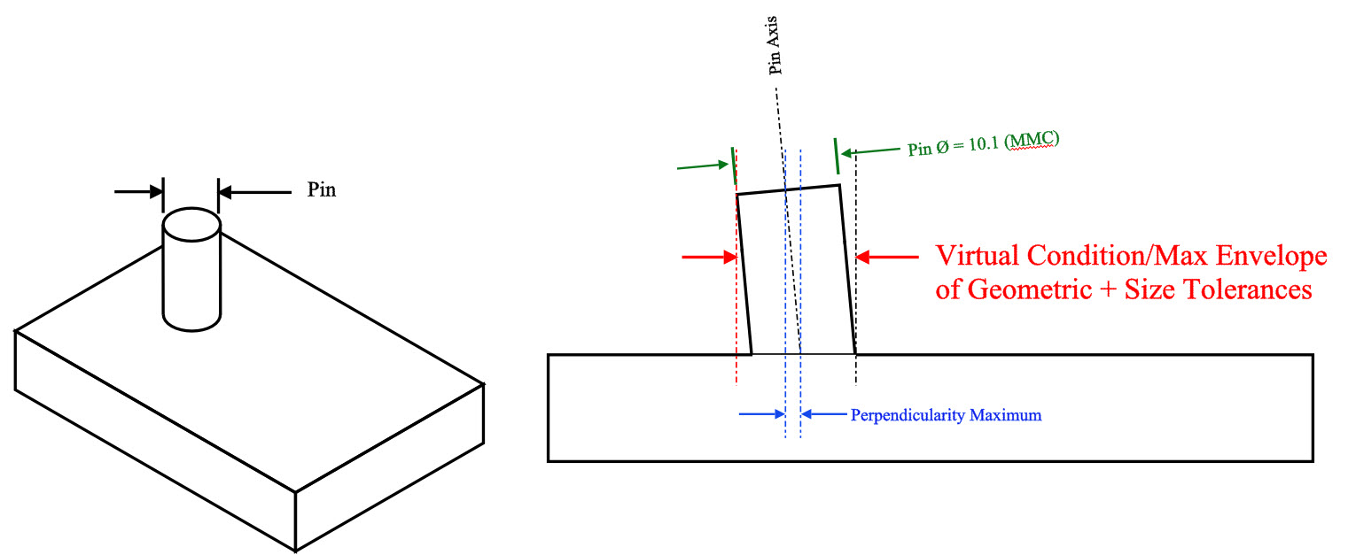
The true benefit of using the maximum material condition on a feature is the ability to call out GD&T with dimensional tolerances and be able to gauge for them at the same time. When geometric control and material control are used together, they form the true maximum envelope or virtual condition that the part can be in and still be to specification.
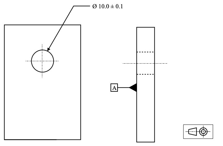
For example, you have a pin with a dimensional and perpendicularity call outs. The pin needs to be within both perpendicular enough and small enough so that it doesn’t get stuck when inserted into its mating hole at a 90° angle to the face of the part. In this case all you really care about is the pin fits into the hole at the worst case limits (MMC and max perpendicularity tolerance make up the maximum envelope of the part)
The virtual condition can be controlled with a functional gauge. Functional gauges can be a huge benefit to production environments where measuring on the line quickly is critical.
Gauging for MMC with Geometric tolerances:
For the Gauging of a hole with perpendicularity call out:
Gauge Ø (pin gauge)=Min Ø of hole (MMC)–GD&T Symbol Tolerance
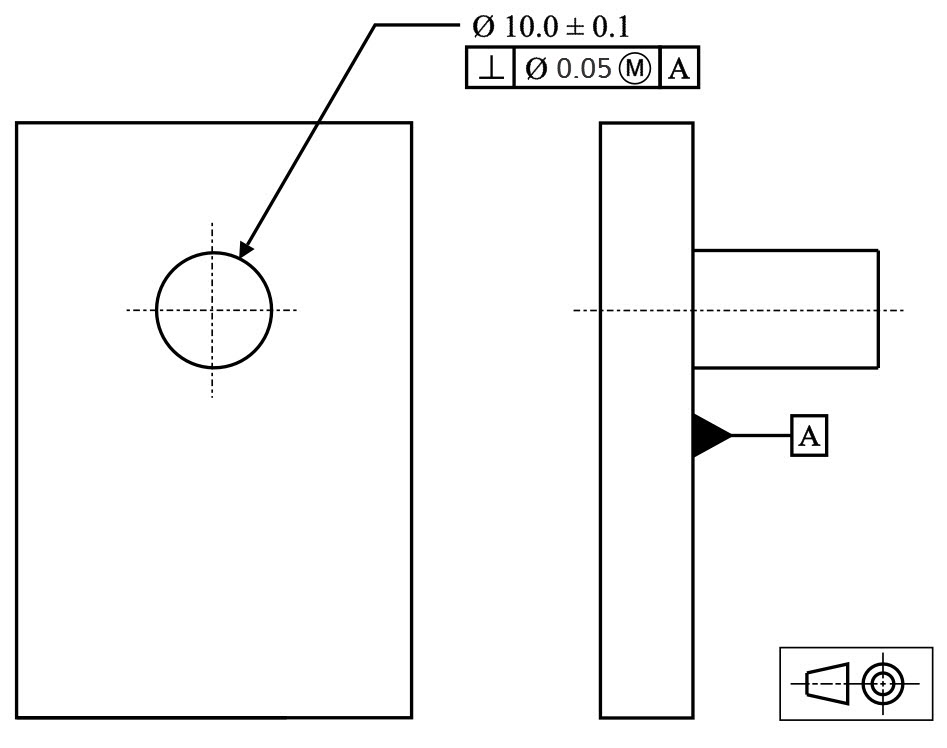
For Gauging of a pin with a perpendicularity callout:
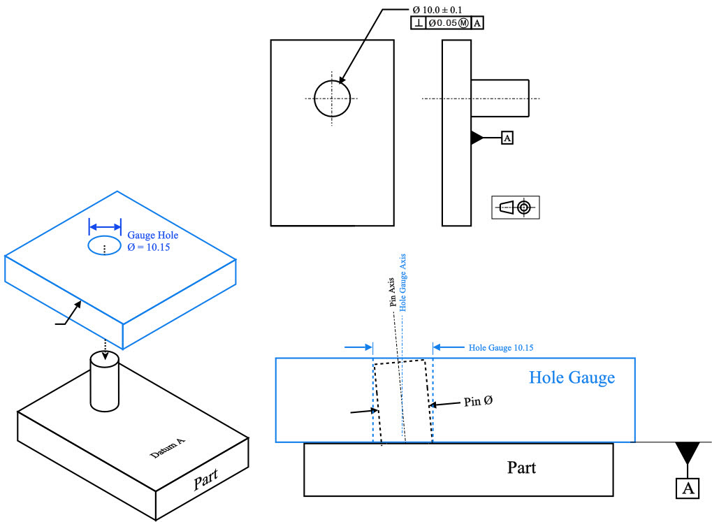
Gauge Ø (hole gauge) = Max Ø of pin (MMC) + GD&T Symbol Tolerance
Note on Bonus Tolerance:
When a functional gauge is used for Perpendicularity, any difference the actual feature size is from the maximum material condition would be a bonus tolerance. The goal of a maximum material condition callout is to ensure that when the part is in its worst tolerances, the Perpendicularity and size of the hole/pin will always assemble together. This means that if you make a pin smaller, you make more bonus tolerance for yourself. This bonus can be added to the GD&T tolerance and would widen the perpendicularity tolerance.
Bonus Tolerance = Difference between MMC & Actual condition
Final Notes:
Features of Size:
Maximum Material Condition is one of three features of size callouts in GD&T. The other two are Least Material Condition and Regardless of Feature Size. All of these specify the condition that the part or feature must be in to apply the specified geometric tolerance.
Default to Regardless of feature size
When there is not call out to Maximum Material Condition or Least Material Condition, the part, by default, is measured regardless of feature size (RFS). This means there is no bonus tolerance and the envelope of the part is not defined. The part must be controlled geometrically regardless of what size the feature is at.
Be The Go-To Engineer at Your Company
Learn GD&T at your own pace and apply it with confidence in the real world.
Get GD&T TrainingAll Symbols


Hi,
Why the modifiers are limited to few , not for all symbols ?
How do you apply MMC to an internal threaded hole location?
Carole –
So you can do this just as with any other clearance hole. Though, I suspect your motivations for wanting to do so may be incorrect. The use of MMC is typically to guarantee assembly as well as to permit the use of functional gaging. The problem with using MMC or LMC with threaded features is that it’s difficult to determine the amount of ‘bonus’ tolerance actually permitted. Really, the only use for MMC in conjunction with an internal thread is to permit the use of functional gaging, as in scenarios where there is a high production volume and a ‘Go Gage’ is desired. You should note that the screw thread rule per ASME Y14.5 states that unless otherwise stated (typically directly below the FCF) the axis of the thread is derived from the pitch cylinder. Lastly, you should note that any tolerance resulting from variation in screw threads is going to be quite small.
I hope this helps, I’m curious to know more about what your design and intent actually are.
Cheers,
Matt
Maximum material condition Doubts
1.What is the thumb rule for adding Material condition modifiers to position tolerance.
Our topic of interest is
a)Is it allowed to give MMC modifiers only to Datum Feature but not not to tolerated feature.
b)Is it allowed to add MMC modifiers to datums which are derived features (plane, line etc which are constructed features).
Regards
Jith Jose
JITH Jose –
So you can add the MMC callout to your feature control frame directly after the tolerance. It then allows for what is commonly referred to as a ‘bonus’ tolerance. It essentially means that as your part feature departs from the maximum material condition towards the least material condition the feature is allowed to be in error by an amount equal to the amount of departure from MMC. The inverse is true with LMC.
However, if you apply the (M) or the (L) to a datum it takes on a whole new meaning. The concept is similar, but it is important to note NOT the same. In these scenarios there are referred to maximum and least material boundaries (MMB and LMB). The easiest way to think of them to help sort your brain out is that as soon as you see them start thinking fixed functional gaging. They are indicating at which material boundary the datum is to be taken at. Now, instead of a bonus tolerance however, the part is allowed to shift in the gage as the datum feature moves from MMB to LMB or vice versa. In some instances this can bring your part in to spec through this datum shift concept and in others you are simply out of luck.
The concept is too complex to try and explain in full detail in a forum question, but I strongly encourage you to take a look at Section 4.11 of the ASME Y14.5 – 2009 standard. I would also suggest you take a good look at both the basic and advanced courses that we offer through GD&T Basics to determine if one or both of those courses is right for you as you look to gain a greater understanding of the concepts at play here.
Keep coming back for more questions! We’ll do our best to answer them.
Cheers,
Matt
Hello Matt,
Thank you for your reply.
Hi Matt,
If a shaft OD is specified 10 -0.01/-0.015 in the drawing, its MMC supposed 10mm or 9.99mm?
Regards,
Jimmy
Jimmy –
This dimensioning scheme is incorrect per ASME Y14.5 standards. I suspect that you have an error in your drawing. You can have a bilateral tolerance, and that tolerance can be equal, (+/-.01), or it can be unequal, (+.010 / -.005). You can also have a unilateral tolerance that can either add, (+.010 /- .000), or subtract, (+.000 / -.010), from the material. Lastly, you can have a limit tolerance 10.020 / 10.000.
Unless I am not understanding your situation correctly that method is incorrect and isn’t doing anything but causing confusion for everyone. I hope that helps.
Cheers,
Matt
Hello, how does a position with MMC work for a slot?
The same Virtual Condition is calculated as it would with a hole, Only now it is linear instead of diametric. Bonus tolerance and VC are calculated the same way – just along a width instead.
Hi Matt
My customer is specifying location tabs on the profile of a part with MMC. This is basically a distance between two points. Is this permissible? We are trying to measure the feature on a CMM and the software does not offer the M modifier as it does if we say measure a circle. Therefore I’m questioning the legality of the call out. Can you advise please?
Tony –
It’s possible I’m misunderstanding your question. You’re asking if the MMC modifier can be used with the profile control? The answer is no, it can not. However, the MMB/LMB modifier may be applied to any of the datums used in conjunction with profile. However, MMC/LMC and MMB/LMB operate in quite different ways.
If I’m interpreting your question correctly I believe the drawing callout to be in error.
I hope this helps, please check back again with your questions and comments.
Cheers,
Matt
Hi All
I need to clarify how do they arrive 0.005 or 0.2 as geometric tolerance, since fits can be calculated using formulas and or based on ISO general tolerance, but how this is chosen. Kindly clarify with example. Thanks in advance.
Nandhajumar –
Unfortunately, I can’t answer that. All tolerances are driven by the design. The designer/engineer work together to determine what the tolerances for a particular part should be. You should only make the tolerances as tight as they need to be in order to ensure functionality of the part. Any looser and the part won’t assemble every time. Any tighter and you aren’t making the part better, just more expensive.
I know this isn’t the answer you were looking for but I can’t honestly provide you with a cut and dry formula to turn to. It really falls into the category of experience and working knowledge of the design details.
Cheers,
Matt
Matt, I have a problem figuring something out based on all the Q and A surrounding this subject. I have a print in front of me giving an Od dimension of 11.731 to 11.711. This also has an MMC of .006 on that OD in connection with perpendicularity. Am I correct in assuming the .006 as it applies to the diameter and the perpendicularity can vary by .006…so long as it does NOT go outside the tolerance range of 11.731 and 11.711?
Input from anyone is appreciated. It would seem odd to call it a “bonus” tolerance of .006 if it cannot be outside the given tolerance range.
Griz –
The OD is listed as 11.711 – 11.731. Under no circumstances can any local size exceed those limits as they are the limits of size. The designer has determined that they want to control the perpendicularity of the feature relative to some datum. They’ve also determined that they want a tolerance zone of .006 while at MMC.
For reference, note that your MMC condition is the one that results in the part being heavier. In your case the MMC is 11.731.
Combining these pieces of information, the control is telling you that at the MMC of 11.731 the axis of the feature must lie entirely within a cylindrical tolerance zone of .006. However, the MMC symbol allows for a bonus tolerance equal to the amount of departure from MMC. This means that if the diameter of the pin is 11.721 you get .016 worth of tolerance and if the pin is at 11.711 you get .026 worth of tolerance.
As long as the limits of size are met and the axis of the pin is within the tolerance zone determined by the actual size of the pin your part is good to go.
I hope this helps.
Cheers,
Matt
When you are figuring a Max material tolerance, how do you calculate it. When the dimension is 5.0 + .5 / -.13 with true position call out of .5 MMC?
Karen –
I’m going to assume you are talking about a hole and not a pin or boss. If I’m wrong please let me know, but the concept will essentially be the same.
For starters, MMC is the condition of a feature that will result in maximum material (i.e. the heaviest part). This would be largest size for an external feature like a pin or boss and the smallest size for an internal feature like a hole. So in your example the MMC of the hole would be 4.87. Now, the tolerance of .5 in the feature control frame is the tolerance that you get regardless of the size of the hole. It’s just always there. When you call out the MMC symbol after the tolerance you are permitting a ‘bonus’ tolerance that is equal to the amount of departure from MMC. This means that if you depart from the MMC condition by .1 (i.e. 4.88) you get an additional .1 of tolerance for a total of .6.
Doing the quick math, the most departure from MMC that you could ever have would be .63. So .63 is the amount of ‘bonus’ tolerance you could get. This results in a total positional tolerance of .63 if the hole was drilled at at 5.5.
I hope this clarifies things for you. Let us know if you have any additional questions.
Cheers,
Matt
In upper example hole dia is 10+/-0.1 that off course MMC of hole is 9.9 If you want to manufacture Go-Gauge for it than Gauge diameter specification should be 9.9 +/- 0.01 by thump rule your should use manufacturing tolerance 10 % of part tolerance.
So gauge tolerance zone should between 9.91 – 9.89 mm.
Hi, Happy New Year! I think you may have missed the fact that the gage would have to be a sleeve and not a pin as the part in question is for a pin and not a hole. When working with functional gages it’s best to first determine the Virtual Condition (VC) of the feature. In this case the VC is 10 + 0.1 + 0.05 = 10.15. This would be the specified size for your gage hole.
I wouldn’t rely on ‘rules of thumb’ for determining tolerances, it will most likely come back to haunt you at some point. There is a special specification out there just for gages and fixtures. I suggest you go take a look at ASME Y14.43-2003 ‘Dimensioning and Tolerancing Principles for Gages and Fixtures’. This standard will tell you what tolerance should apply to the VC value determined earlier.
I hope this helps.
Cheers,
Matt
Why can’t I have an MMC for circularity? In many situations, I can allow a higher circularity error if the dia is bigger.
Dhanish –
Manu’s comment from a little earlier is correct. Circularity is independent. You are measuring the produced shape to two co-axially located perfect circles a distance T apart. Where T represents the value from the feature control frame.
As for why MMC isn’t allowed, I really don’t have a better answer other than that is simply the way the standard is written. The concept of MMC is really there to ensure assembly while making allowances for manufacturing.
Let us know how else we can help.
Cheers,
Matt
What do i use for a locating size for a hole that is called say .266dia. +.001/-.002 with a true position of .005. There is no mmc or LMC on htis dimension and its datum C on the print. I don’t know if I use .266 and subtract the true position or if I need to subtract the .002 from the diameter and the .005. I can’t remeber this one. Any help?
Matt –
Are you trying to determine the inner boundary for tolerance stack purposes? For an internal hole it’s the MMC size of the hole (.264) minus the positional tolerance (.005). The result is .259.
Hope this helps. Let us know otherwise.
Cheers,
Matt
Hi explain any one of the GDT symbol with MMC….
Anand –
MMC and LMC stand for Maximum Material Condition and Least Material Condition. To avoid confusing the difference between internal and external features think of MMC as the condition which makes the part heavier (i.e. smallest hole size for an internal feature and largest ‘pin’ size for an external feature) and LMC as the condition which makes the part lighter (i.e. largest hole size for an internal feature and smallest ‘pin’ size for an external feature).
Not all geometric symbols can use the MMC/LMC modifier (position is one example may use it and flatness would be an example that can not use it). Now, the cool thing about MMC/LMC is that they permit a ‘bonus’ tolerance in addition to the value stated feature control frame just to the left of the MMC/LMC symbol. This bonus tolerance applies as you depart from the stated material condition (MMC/LMC) towards the opposite end. The amount of ‘bonus’ tolerance is equal to the amount of departure from the specified material condition.
For example, say you have a through hole in a bracket with size 5 +/-1 and a positional tolerance of diameter 1 at MMC. Your MMC hole size is 4 and you are provided no additional tolerance through bonus. Now, if vendor only has a 5 drill bit you still get the 1 positional tolerance zone but now you get another 1 for a total of 2. If the hole comes in at 6 you get the stated 1 plus 2 for a total of 3. No matter what, you always get the 1 and any additional tolerance is the result of the actual hole size drilled into the part.
Why does it work this way? The goal here is assembly. If you calculate that you can live with a hole of size 4 and tolerance of 1, then it should make sense that as your hole grows in size you would be able to tolerance an increase in the tolerance zone while still protecting assembly.
LMC works in the same way, just in the opposite direction and can be used to protect wall thickness of say a bore in rod.
I hope this helps! Keep cruising the forums and website. Let us know if you have any other questions.
Cheers,
Matt
Hello, can you put also a presenation with MMC on a datum ? for example, true position 0.5 MMC | datum A | B MMC | C ? I think that will be common in the near future. Thank you !
How does MMC apply to TRUE POSITION
MMC or Maximum Material Condition like its counterpart (Least Material Condition [LMC] ) is specifying at which physical condition the stated tolerance in the feature control frame applies to a specified feature. Think of MMC as the condition that results in a heavier part, i.e. smallest size for an internal feature, like a hole, and largest size for an external feature, like a boss. Now, as the feature size moves from MMC towards LMC you gain additional or ‘bounus’ tolerance in which the feature axis or plane must be located within. The amount of bonus tolerance is equal to the amount of departure from the stated MMC or LMC in the feature control frame.
Example: If you have a 1 +/- 0.1 hole with a positional tolerance of 0.1 at MMC, your MMC condition is 0.9. The bonus tolerance available is 0.2 (1.1 – 0.9 = 0.2). The total tolerance available at 0.9 dia is 0.1 and at 1.1 dia is 0.3.
Why does this work? Well, the goal here is functional assembly, so with MMC called out doesn’t it make sense that if I have a larger hole a larger tolerance zone would result while still allowing for a pin or fastener to fit?
If I am measuring an ID hole with a tolerance from .2-.205 with a true position of .01 at MMC, is there an allowance for out of roundness of that hole as long as it falls into the maximum material boundary? For instance, if the hole is out of round at it’s largest point is measuring .208 but a gage pin of .203 is the largest pin that fits into that hole, is the part out of tolerance?
Technically, yes. Your limits of size specify just that, limits. The positional tolerance applies to only the hole position, it has no impact on the size. The size, if specified with either MMC or LMC, can have a direct impact on the tolerance however. As for the impact to the design? That really depends on what the design is for, I would wager most applications would be fine with it. Ultimately, the discrepant condition should be written up and flowed down to the customer to evaluate and disposition.
Hope this helps.
Cheers,
Matt
I have seen parts where there is MMC called out for positional tol and some that do not have MMC callout on positional tol. When there is no mmc called out, say on a L bracket with a hole on one side 10mm +/-0.2 and has a position tol of 0.5 with respect to the base as the datum. Here if there is mmc on the positional tol, part at 10.2 hole, it has a bonus tole of 0.2+0.5 positional tol it gets. But if there is no mmc symbol used on the positional tol box, and the part measured at 10.2 does not get a bonus tol?
Colleen –
Only when the MMC or the LMC symbol is called out do you get a ‘bonus’ tolerance. If neither MMC/LMC is called out all the tolerance you get is from the value stated in the tolerance block of the feature control frame.
A minor correction on your statement above. MMC refers to maximum material condition. The best way to think of this is the condition that will make the part heavier (i.e. smallest size for an internal feature and largest size for an external one). With MMC/LMC called out you are allowed a ‘bonus’ tolerance equal to the amount of departure from MMC. In your specific example you always have a tolerance zone of 0.5. The MMC size of the hole (internal) is 9.8. At a diameter of 9.8 you only get 0.5 for tolerance, at 9.9 you get 0.6 and at 10.2 you get 0.9. Make sense?
The way this works is all about assembly at the next higher level. You know that at your MMC size and tolerance you are guaranteed a fit (if you calculated it correctly), every size must have tolerance so if your hole is slightly larger it should make sense that you would be able to accommodate an increase in positional tolerance as well and still have everything fit together.
I hope this clears things up, let us know if you have any additional questions.
Cheers,
Matt
dear sir please help to measure dia of 23 +0.045 with concentricity Ø2.0 mmc w.r.t datum
Pratap –
I take it since you’re asking you don’t have access to a Coordinate Measuring Machine. This would be the easiest way to inspect this control. The MMC/LMC modifier is not allowed to be used in conjunction with concentricity, so that needs fixed.
As for how to measure it the old school way: First, fixture your part so that the chuck/collet/spindle etc is grabbing your datum. You should be able to rotate your part a full 360 now. Second, get two dial indicators and set them up so that they are diametrically opposed of one another on the controlled surface, for this example lets say put the indicators at 0 and 180 degrees (straight up and down). You need to be able to set up the indicators such that they start at a radius of 11.5 and have enough stroke in and out to accommodate your range of tolerance. Now, as you spin your part you get two measurements from your dial indicators and these tell you what the local radius is from the datum axis (pay attention to whether you are adding or subtracting from nominal based on dial indicator plunger movement in or out from your nominal 11.5). Now, add these 2 dimensions together and divide by 2 to get a number we call r0. Subtract r0 from your measured local radius (from the 0 deg indicator) and you have your concentricity error Co. Every distance Co must be within the cylindrical tolerance zone defined in your feature control frame.
Keep in mind that you are not done, in addition to the measurement you just made you need to make sure that the local size is within limits at all places (23 +/- .045) and that you are not violating what we call Rule #1 (perfect form at MMC).
I hope this helps. It’s a little complicated, but read through a time or two and you should be able to replicate what I’m talking about.
Cheers,
Matt
What’s meen by mmc and explanation ….I am not understand above
Think of MMC (maximum material condition) and LMC (least material condition) this way. For a feature of size (hole, pin, tab, slot etc.), the MMC is the extreme limit of size tolerance that would make the part heaviest and LMC is the extreme limit of size tolerance that would make the part lightest. So for a pin with a diameter of 1 +/- 0.1, the MMC is 1.1 and the LMC is 0.9. For a hole with a diameter of 1 +/- 0.1, the MMC is 0.9 and the LMC is 1.1.
I hope this clears it up, let me know if you have any additional questions about this.
Matt
Could you help with the functional pin gage formula in the following condition ?
– block with 2 holes on opposite sides of same diameter (7mm) +/- 0.2mm tol, spaced by 50 mm
– has an additional true position tol of 2 mm from the edges taken as datums, a composite true position tol of 0.2
– with an additional parallel tolerance of 1mm to the edge?
Thankyou!
Colleen – I’m not sure I fully understand what your part looks like. Would you mind sketching it up and sending me the image at ? I need additional information “are are the positional tolerances at MMC, what is the datum structure for each segment of the composite control etc.” These will influence what your gages looks like. Note that with a composite or multiple single segment control the individual segment requirements are verified separately. Sorry for the delayed reply, I’ve been on vacation and just got back. Thanks for your patience.
Matt
Sorry Matt, it took a bit to get back here, so the part has a baseplate and 2 side plates welded to the base (90 deg angle). These 2 side plates are separated by 200 mm and they each have 2 thru holes (50mm-50.2) machined, and each hole on the side sheet has a position tol 3mm @ MMC with respect to the bottom base plate as the prime datum, and a composite tol of 0.2 to the hole on the opposite side sheet. this hole is now a new datum, B and is used to locate the other hole on the same side sheet of same dia. This one has a position tol of 2mm with respect to B at MMC (mmc is called on the tol and the datum). This again has a composite tol of 0.2 to the other side sheet hole and a parallel callout to B within 1mm. We are trying to come up with a gauge to check the second hole position relative to B within tol and Is parallel to B within tol. Thoughts?
Colleen –
Can you send me a sketch or a drawing at ? I’m not positive I have a grasp on your exact situation.
Plz ,
Sir
Details for mmc with example more confusion in mmc reading drawing that this is use for hole or pin.
Thank you very much for your clear explanations! Please help me understand one issue – what if there was a pin specified on a drawing with diameter 10+/-0.1 and produced slightly conical, so that on one end it is 9.9 and on the other 10.1? Will it be concidered as produced at mmc? Or maybe lmc? What if it was called out with straightness at mmc? Will it get bonus tolerance for the sections where the diameter is less than 10.1? And what if the call out was true position or perpendicularity with mmc? Would there be any bonus tolerance allowed? Thank you very much in advance, simon.
Hello Simon – The MMC is a measurement of a two points. The part would actually be both depending on where the measurement was that made it You would usually take the boundary condition of the part which would be the MMC. According to the envelope principle your part cannot go outside of its MMC envelope, and cannot have any 2 point measurement less than the LMC.
Now bring in straightness at MMC. The design intent is that you are specifying the combination of the worst geometry with the worst size. So if you were to inspect the part, you would need to make 2 measurements. First is using your straightness gauge set at 10.1 + straightness tolerance. If the part fits, the straightness is met. Next your part would be measured for size. No 2 point measurement could be above 10.1 or below 9.9. If these pass your part is in spec. The true is that yes, you would get bonus tolerance as your part diverts from MMC, so one side could be less straight than the other. The goal is that it fits into its assembly meaning the straightness and size cannot allow it to exceed a certain limit. This works because straightness is not datum controlled.
Position and Perpendicularity would be fairly similar, only it would depend on the same 2 measurements Position and size would all have to be met independently. This means that if your part is at MMC (with a zero Perpendicularity Tolerance) your part would need to be perfectly perpendicular. (unless the thin part was on top, and angled just so that the bottom was centered and the top was not too out of position. For datum controlled features, the rule typically is that it would be considered as a MMC part – since it could not move anywhere if it was set in a functional gauge.
Matt, thank you very much for the answer, now i understand it!
How does mmc apply to paralleism
MMC can apply by allowing the parallelism tolerance to increase for a feature of size as the size moves away from the MMC.
I’m confused. Base on the example above, so what are the MMC values of
1. Gauge Ø (pin gauge)=Min Ø of hole (MMC)–GD&T Symbol Tolerance=??? (Diameter of the pin)
2. Gauge Ø (hole gauge) = Max Ø of pin (MMC) + GD&T Symbol Tolerance=??? (Diameter of the hole)
The example shows how to calculate the Gauge size, also known as the Virtual condition. The term maximum material condition means the largest external feature or the smallest internal feature. For a pin, its largest size is considered the MMC. The tolerance given in the feature control frame applies to this size. As you get smaller in size, you are allowed to add whatever the differences is between your actual size and the MMC, to your geometric tolerance.
Hi Geisstc,
What does it mean when there’s a GD&T true position .000 MMC?
This is a call out on the threads I’m grinding for. FWIW, I’m grinding these between centers. Can this also be translated to a concentricity tolerance?
True position of 0 simply means that at Max Material Condition (largest pin or smallest hole your part must be perfectly centered. Ultimately you should target the LMC of the part (Smallest pin or largest hole) so that you can be out of position more. For example if your tolerance on the hole is 10 + 0.5 if you had a hole of 10.0 your location would have to be perfect, but with a hole size of 10.5 you can be out of position by 0.5.
On the Maximum Material Condition page, the gauging of a pin with MMC seems to have an error, or I’m misunderstanding it. The diameter of the hole gauge to use is stated to be equal the feature diameter plus feature tolerance plus GD&T tolerance (to gauge the maximum material of the pin). The drawing has a 10.0+/-0.1 feature callout with GD&T tolerance of 0.2 perdendicularity. Wouldn’t that make the hole gauge be 10.3 in diameter, not 10.15 as shown in the example?
Your 100% Correct -Its a typo, The example was supposed to be the same as the one below for the hole @0.05, Sorry for the confusion! Thanks for spotting it and letting me know! Should be fixed now.
The gauge hole in the final example (“For Gauging of a pin with a perpendicularity callout”) the gauge hole size still reads 10.15. Is this the same typo you were referring to? A pin with 10+/-0.1 diameter with a 0.2 perpendicularity MMC should be gauged with a 10.3 hole, correct?
Good Catch- you are right – we changed this example a while back to simplify it and the second drawing never was swapped with the new one. Thanks for the help with pointing this out!