

What is the difference between unilateral and bilateral tolerance in a profile of a surface callout? In this post, Brandon explains the difference and gives examples of how they are used.
Profile of a Surface
When applying a 3-Dimensional tolerance zone around a surface, usually a curved shape but could be any, the Profile of a Surface symbol is used. The profile of a surface symbol is a half-circle with the curved edge facing up and the flat edge on the bottom. On the feature control frame, the box to the right of the Profile of a Surface symbol contains the tolerance for the surface. The tolerance zone consists of two parallel profiles that follow the True Profile. The tolerance zone can be bilateral or unilateral.
Bilateral Tolerance Zone
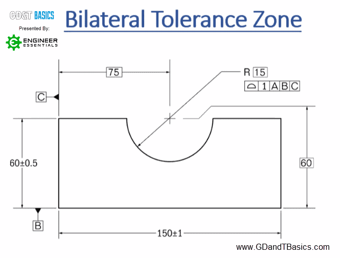
In a Bilateral tolerance zone, the tolerance shown in the feature control frame is the total tolerance zone. The true profile is established with basic dimensions, and the tolerance is equally disposed from the true profile. Figure 1 shows a part where the Profile of the Surface has a Bilateral tolerance zone. In this example, the profile of a surface tolerance is equally distributed about the radius, which has a basic dimension of R15, and the total tolerance is 1. This results in a tolerance zone with an upper radius of R14.5 and a lower radius of R15.5.
Unilateral Tolerance Zone
Where a Bilateral tolerance zone has a tolerance that is equally disposed from the true profile, a unilateral tolerance zone has an unequally disposed tolerance. The same part shown in Figure 1 is shown in Figure 2, with a Unilateral tolerance zone.
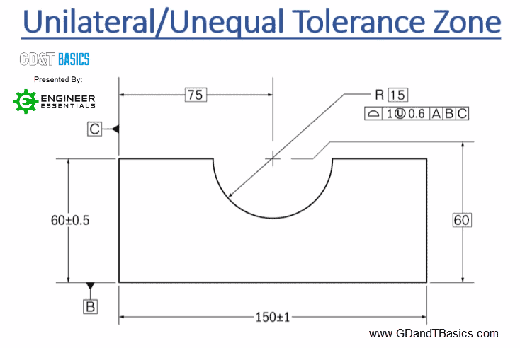
You can see that the feature control frame has the addition of the Unilateral symbol (a circled “U”) to the right of the tolerance. There is another number given on the right of the Unilateral symbol. The value to the left of the U is still the total tolerance. The value to the right of the U is the portion of the total tolerance that adds material to the part. For the example in Figure 2, the total tolerance for the profile of a surface applied to the radius is 1. The tolerance given to the right of the U symbol, 0.6, indicates that 0.6 must be subtracted from the radius to provide the maximum material condition of R14.4. Because the total tolerance is 1, subtract 0.6 from 1, which gives the amount of remaining tolerance that will remove material from the part. This results in a tolerance zone of R14.4 to R15.4.
The U modifier symbol to show unilateral tolerance zones was added in the 2009 ASME standard. Prior to this, the 1994 ASME standard used the “Phantom Line” method to show unilateral tolerance zones. Figure 3 shows the part from Figure 2 with Unilateral Tolerances shown using the Phantom Line method.
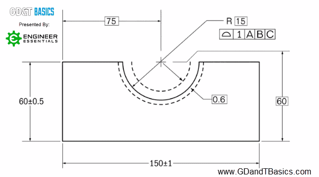
Using the Phantom Line method, the tolerance zone’s upper and lower boundaries are shown on the drawing using phantom lines. The feature control frame is the same as that for a Bilateral tolerance zone, with the total tolerance shown. However, the tolerance dimension that adds material to the part, 0.6, is shown on the drawing as a basic dimension.
The phantom line method is still an acceptable practice as an alternative to using the U modifier symbol. It is straightforward to understand, so if you are working with someone less familiar with GD&T, indicating a unilateral tolerance zone this way may be a better option. However, the preferred method is to use the U modifier as outlined in the 2009 ASME standard.
Additional Unilateral Tolerance Zone Examples
When teaching about Unilateral Tolerance zones, we commonly get questions about how the tolerance zone is affected when the value to the right of the U modifier is equal to the total tolerance and when the value is equal to zero.
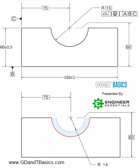
If the total tolerance and the value to the right of the U modifier are the same, it means that the total tolerance will be adding material. There will be no tolerance for taking material away from the basic dimension. An example of this is shown in Figure 4. The radius basic dimension is R15, so with a value of 1 to the right of the U modifier, the resultant tolerance zone would be between a radius of R14 and R15. Setting the tolerance in this way can be useful for castings because if toleranced appropriately, it would guarantee that the part could be cleaned up without violating the basic dimension.
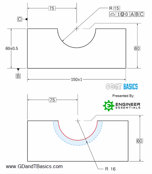
In the next example, the value to the right of the U modifier is equal to zero, as shown in Figure 5. Setting tolerance in this way ensures that no material will be added. The total tolerance will be for material taken away from the basic dimension. In this example, the radius has a basic dimension of R15. With the zero tolerance for material added to the profile, the tolerance zone would be between a radius of R15 and R16.
The one-page GD&T reference that you will use every day
A visual breakdown of every core GD&T symbol and what it controls, all on one page. Bookmark it. Print it. Actually use it.
Download the Chart