
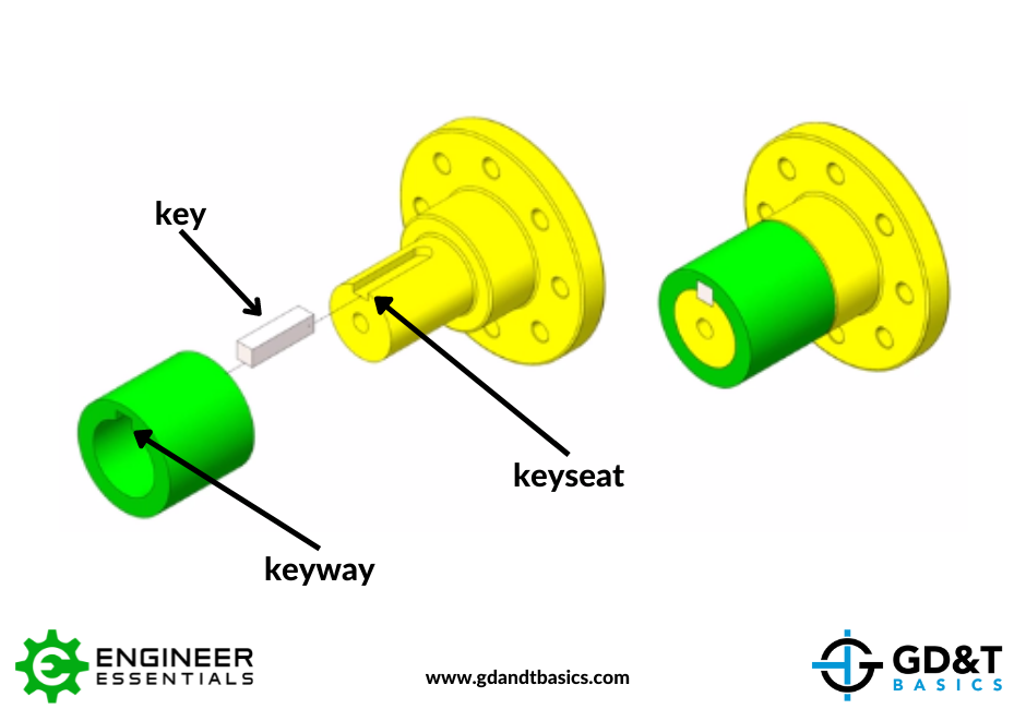
A keyed joint is used to ensure orientation or restrict rotational movement between parts, as in the case of joining a shaft with a coupling. To create a keyed joint, a key is used that fits between slots manufactured into the two parts being joined. The slot is defined as a keyway or a keyseat, depending on the whether the slot is located on an internal or external feature. Slots created by removing material on an internal cylindrical feature are called keyways. Slots created by removing material on an external cylindrical feature are called keyseats.
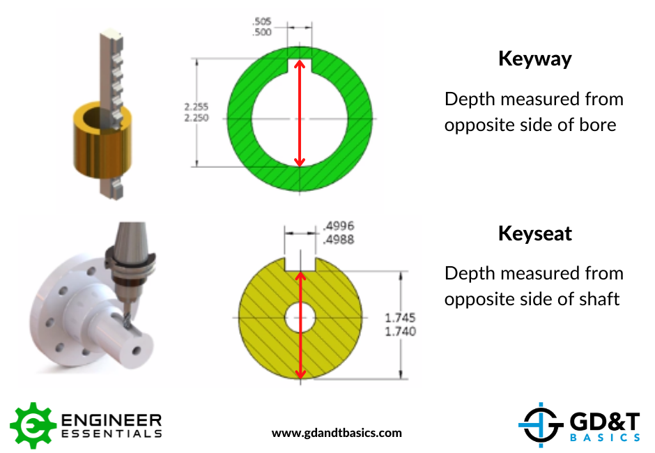
When indicating a keyway or keyseat on a drawing, the depth, width, and location should be specified to give the full size and location of where the cut is to be made on the part. In the figure below, notice that the depth of the keyway is indicated from the opposite side of the bore, and the depth of the keyseat is indicated from the opposite side of the shaft in these models. It is a best practice to indicate the depth of the slots in this way so that when manufactured, the local size of the slots can be easily measured with a set of calipers or micrometers.
Keyed joints are simple connections requiring high precision. Indicating them correctly on a drawing will ensure that the design intent is correctly inspected and verified.
Watch our YouTube video explanation of keyways and keyseats below:
Want to Learn More About Drawing Callouts?
Check out our Print Reading and Tolerances Course
LEARN MORE