
 Straightness can be used 2 ways. First, it can be used as a 2-Dimensional tolerance that controls the linear cross–sectional elements of a surface, as well as the linear elements of a cylinder along the axial direction. It can also be applied to control the derived median line of a cylinder. It is ensuring these elements are straight within a defined tolerance.
Straightness Symbol and Callout
Surface Straightness
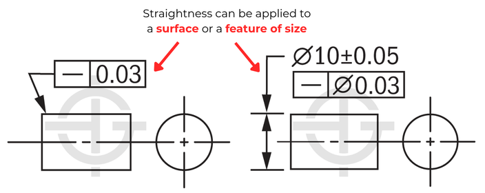
The standard form of straightness is a 2-Dimensional tolerance that is used to ensure that a part is uniform across a surface or feature. Straightness can apply to either a flat feature such as the surface of a block, or it can apply to the surface of a cylinder along the axial direction. It is defined as the variance of the surface within a specified line on that surface.
Feature of Size Straightness
The form of straightness that controls the bend of the central axis of a part is referred to as Derived Median Line Straightness. This tolerance callout specifies how straight the axis of a cylindrical feature is. By definition, DML straightness is actually a 3D tolerance that constrains the center axis of the feature by preventing it from bending or twisting beyond a cylindrical tolerance zone. Notice in order for the control to be applied to the derived median line, the feature control frame is attached directly to the size dimension, rather than the surface of the feature.
Straightness Tolerance Zones
When applied to a feature of size versus the surface of a feature, the tolerance zone for straightness will change. How the feature control frame is applied will dictate the interpretation.
Surface
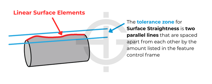
When applied to any surface, cylindrical or planar, the tolerance zone is a set of parallel lines where the individual linear element of the surface must lie. The tolerance zone is established parallel to the view the control is applied in, or in the case of cylindrical surfaces, the tolerance zone is coplanar to a plane that intersects the center of the feature. It is also unconstrained to any other features and related only to itself.
Feature of Size
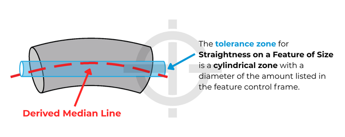
When applied to a cylindrical feature of size, the tolerance zone is also a cylinder where the entire derived median line must lie. The tolerance zone is unconstrained to any other features and related only to itself.
How to Inspect Straightness
Surface
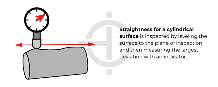
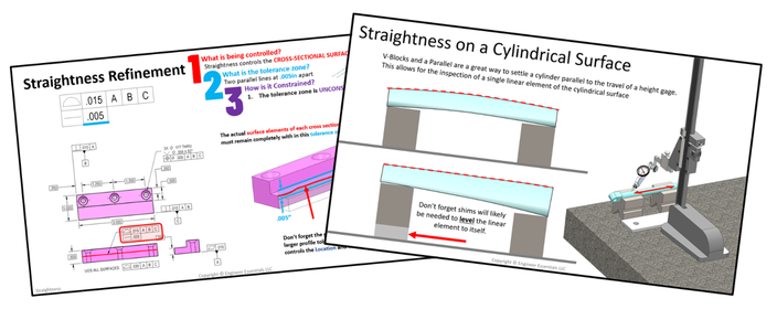
Straightness can be measured using a height gage or indicator that you then run along the cross-sectional elements of the referenced surface one by one. The measurement of each cross-sectional element is taken independently of other elements. Care should be made to ensure the element being measured is leveled to the granite table or the surface that the indicator is translated on.
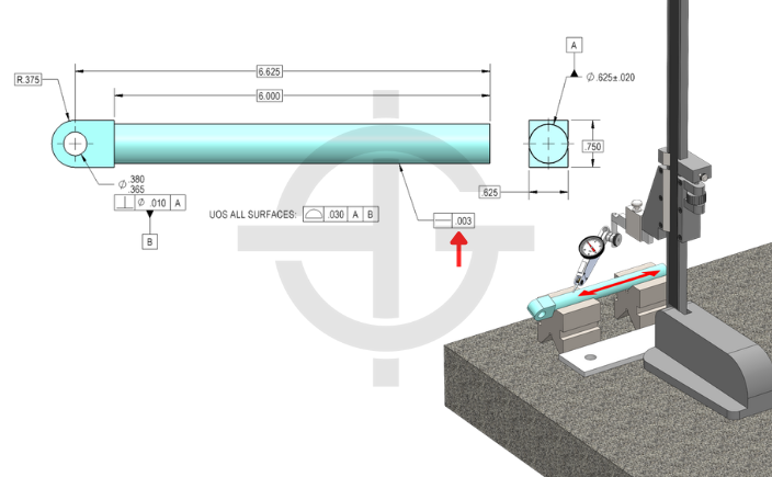
Modern CMM’s are even quicker for measuring the part as they can mathematically determine the deviation of any surface element with respect to itself.
Feature of Size
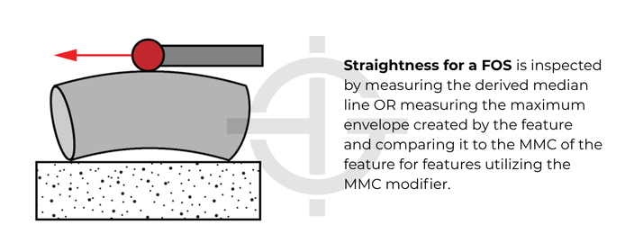
DML Straightness is inspected by evaluating the central elements of a derived median line. It is unconstrained, not related to any datums. Generally, a CMM is the best option for inspecting DML Straightness. When the MMC Modifier is added to the tolerance, a constant boundary is created at the feature’s Virtual Condition, and verification with a height gage is very achievable.
Example and When to Use Straightness
Most commonly, straightness is used to refine the form of cylindrical features. Don’t forget, Rule #1 already controls this and other form controls, however sometimes form is even more important than size. Straightness allows a designer to refine ONLY the form control to be tighter than the allowed size tolerance. It is useful when a design requires immense control of the barreling, waisting, or bowing of cylindrical features. (Cylindricity can also be considered for this type of control as they are loosely related.)
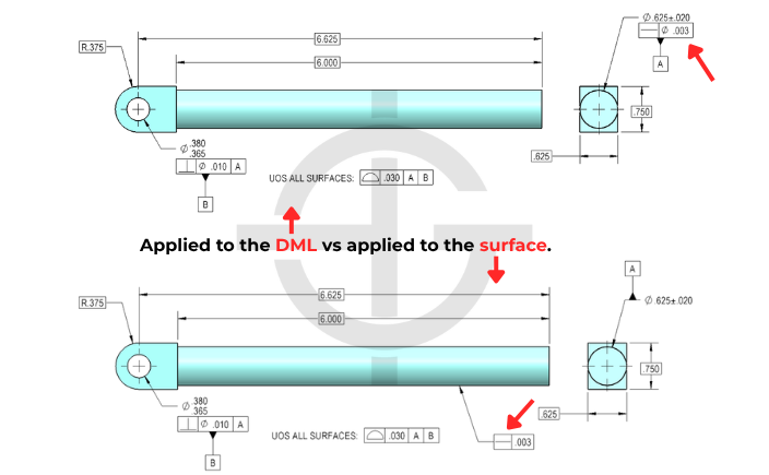
The choice of applying straightness as a feature of size control vs surface control for a cylindrical feature is a tricky one. In fact, if tolerance values are appropriate, they can BOTH be applied to a feature at the same time, both controlling difference aspects of cylindrical form. Care must be taken during the design process to ensure proper tolerances are selected to support the function of the part.
We cover the intricacies of straightness, how it’s interpreted, how it’s inspected, and the miscellaneous things you should know about this symbol in our GD&T Fundamentals Course as well as our GD&T Inspection Course. These courses show you everything you need to know about straightness and then some!

All Symbols