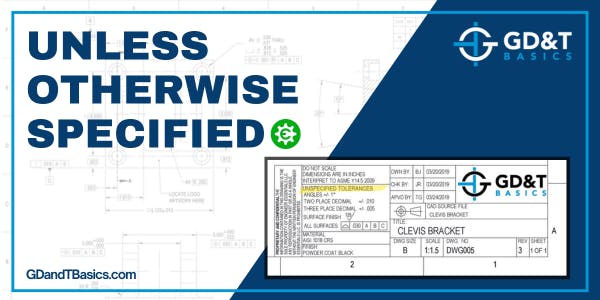
Does the CAD Model or Drawing Information Take Precedence?
In this Question Line video, Jason discusses how to approach situations where the CAD model and drawing information do not match, and how to determine which takes precedence.
Articles related to reading engineering drawings and interpreting GD&T on the prints
In this Question Line video, Jason discusses how to approach situations where the CAD model and drawing information do not match, and how to determine which takes precedence.
In this Question Line video, Jason reviews a submitted drawing, explaining the difference between flatness and parallelism, and gives options on how to tolerance the drawing based on what is critical to the design.
What does it mean when a dimension is circled on a drawing—and how does it impact manufacturing? In this video, Jason explains the informal use of ovals as quality control symbols and what it means for how parts are made and inspected.
In this Question Line video, Jason answers the questions regarding the use of the Unless Otherwise Specified (UOS) statement on a drawing.
In this Question Line video, Jason answers a student's question regarding whether a default angular tolerance (found in the Title Block) must be taken into account in addition to the part meeting Rule #1 for it to pass inspection.
In this Question Line video, Jason introduces ASME Y14.8 and explains how to apply + or - DRAFT to size dimensions, using examples to show how to find and handle tolerances for draft features.
In this Question Line video, Jason explains the difference between locating features using GD&T and doing so with traditional coordinate dimensions. He walks through two example drawings to show when to use GD&T and the benefits of it over traditional coordinate dimensions.
In this Question Line video, Jason compares coaxiality, concentricity, and position as defined by the ISO 1101 standard. The ASME Y14.5 interpretation of concentricity and coaxiality is very different from ISO and is not presented in this video.
In this series, we will explore the most common errors that we see in implementing GD&T on engineering prints, and provide you with practical solutions to avoiding these pitfalls.
Jason explains how to tell at a glance whether a drawing has inch or metric dimensions in this Question Line video.
"Why isn’t Maximum Material Condition always just the largest size the feature can be?” Jason answers our student's question and gives us a delicious way to remember the MMC state in this Question Line Video.
Is it possible to control multiple identical profiles by including a multiplier with the feature control frame? In the video below, Jason reviews a drawing with 2 irregularly shaped identical cutouts to answer this question.
In this question line video, we explain when to use the diameter symbol in a feature control frame. The examples below illustrate the unique tolerance zones shapes and sizes for position, perpendicularity, straightness, runout, and cylindricity controls.
Surface finish and flatness both limit the amount of variation in a surface – one at the micro level and one at the macro level. Is it permissible to call out both on the same surface?
In our video question line, our GD&T instructors answer questions submitted by our students. In this video, we answer the question, “Is the Virtual Condition the same as the Tolerance Zone?”
A chamfer is an edge feature commonly seen on part drawings, and consists of an angled cut on an internal or external edge of a part.
Fillets and rounds are both radial edge features, with fillets applied to internal edges and rounds applied to external edges.
“Break all sharp edges and remove all burrs,” is a common drawing note used to notify the manufacturer that the sharp edges and burrs produced by the manufacturing process must be removed from the part.
Knurling is a process used to create a pattern on the surface of a material by displacing or deforming the surface.
To understand the thread requirements on your drawing, you need to know common standard thread information. In this article, we will be discussing thread diameters, threads per inch and thread pitch.
Precision tops the list of priorities in CNC machining since being off by a few thousandths is enough to cause serious errors. While no machine yields a 100% accuracy rate, specific approaches have been undertaken to manufacture components efficiently and economically.
A keyed joint is used to ensure orientation or restrict rotational movement between parts, as in the case of joining a shaft with a coupling. We discuss how a keyed joint is made and inspected in this article.
In this article, we outline the basic process for adding GD&T to your drawing using SolidWorks. The accompanying video goes into full detail, walking through the entire process for an example drawing.
Some parts, such as those made of rubber or sheet metal, may fail inspection due to deformation from gravity if left in their "free state." This can be prevented by invoking a "restrained state."
Though many people refer to the GD&T Position symbol as "True Position," they are not the same thing. Read on to learn the difference between Position and True Position and how they work together to define the position of a feature.
We get a lot of questions from students asking why they would want to use Geometric Dimensioning and Tolerancing (GD&T) over coordinate dimensions. Some believe that using GD&T will result in tighter tolerances and increase...
What is a Datum Reference Frame? Datums are used in Geometric Dimensioning and Tolerancing drawings to create a reference system for inspecting a manufactured part. This reference system is called a Datum Reference Frame (DRF)....
Having a good understanding of Geometric Dimensioning and Tolerancing is very important for anyone working in a mechanical field. GD&T is the language used in design, manufacturing, and quality inspection to communicate on engineering prints....
The most common way to produce an internal thread is to drill a hole and then use a tap to produce the thread. This is usually referred to as a tapping drill for the size...
Geometric dimensioning and tolerancing (GD&T) is a system in manufacturing that can be traced back to the 1940s. It was developed by Stanley Parker while he worked at Royal Torpedo Factory in Alexandria, West Dunbartonshire,...
How are tolerance limits defined? The previous articles in our Intro to Tolerances series have answered the questions, “What is a tolerance?” and “Why use tolerances?” This third and final article in the series explores...
Why use tolerances? In our previous article, “What is a Tolerance?” we introduced the concept of manufacturing tolerances and why they are necessary. In this article, we are going to focus on the benefits of...
What is a tolerance? If you take a look at an engineering drawing, you will notice that there are always limits, or tolerances, placed on a dimension. Why does the designer do this? When a...
What is GD&T? If you are involved in design or manufacturing, you may be familiar with the term, “GD&T,” or “Geometric Dimensioning and Tolerancing”. Geometric Dimensioning and Tolerancing is a set of rules and GD&T...
Orthographic views allow us to represent a 3D object in 2D on a drawing. Orthographic views can show us an object viewed from each direction. How the views are laid out on a drawing depends...
A question we are often asked here at GD&T Basics is, “what is a basic dimension?” – These dimensions are often fairly confusing as they look very similar to other dimensions you may be familiar...
This post is in response to a question that we received on our question line from Gilroy. Gilroy asked us about the drawing projection method in an example problem that was a part of our...
Surface finish can be a confusing subject, especially when it comes to units or the difference between Ra and Rz. In this article, we will provide a broad overview and answer some of the most...
Everyone understands the simple plus or minus tolerances of coordinate dimensioning. So why use GD&T instead? Here are four reasons that GD&T has an advantage over coordinate tolerancing… What are the advantages of GD&T...
**As of April 1, 2022 – Engineering Drawing Basics has been renamed to Print Reading and Tolerances. The course content did not change, we simply updated the name to better reflect the product.** Engineer Essentials,...