
Everyone understands the simple plus or minus tolerances of coordinate dimensioning. So why use GD&T instead? Here are four reasons that GD&T has an advantage over coordinate tolerancing…
What are the advantages of GD&T vs. Coordinate Tolerancing?
Coordinate dimensioning is easy to read and understand. It’s the way most of us have learned to create drawings and is what we are familiar with. So, why make a change? Why would we not want to use simple plus or minus tolerances to locate features on a drawing? When should we use GD&T instead? In this article, we are going to discuss four benefits to design and manufacturing by applying GD&T in drawings rather than using coordinate tolerancing. The first three points of this article are also discussed in this video: Using True Position vs. Coordinate Dimensions.
1. Clear Measurement Requirements
When it comes to the inspection of a part, GD&T has a great advantage over coordinate tolerancing. With coordinate tolerancing, dimensions of the part are given, but the drawing does not indicate how the part is to be set up for measurement. This can result in very different measurement values for the same part. Take the part drawing in Figure 1 as an example. The coordinate dimensions give the location of two holes. Based on the drawing, how would these holes be measured?
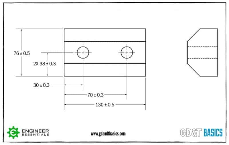
Figure 1: Coordinate Dimensions on a Part Drawing
The location of these holes could be measured in multiple ways because it is not specified on the drawing. Figure 2 shows two ways this part could be set up for inspection.
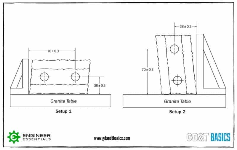
Figure 2: Measurement Setups
You can see that the ends of the manufactured part are not perpendicular to the long edge of the part. Because of this, the measurement location of the holes in setup 1 would result in different values than what would be measured using setup 2.
So how does GD&T solve this issue? The answer – datums. A datum is a theoretical plane, axis or point that is used to establish a datum reference frame that dimensional tolerances are referenced to. It is called out on a drawing as a capital letter with a box around it. Datums on a drawing show how the part is to be setup for measurement.
Let’s look at another example. Figure 3 shows a drawing of a part with four holes, using coordinate dimensions. The measurement setup is not specified on the drawing, and based on what we learned above, different setups could provide different measurement values for the location of the holes.

Figure 3: Part Drawing Using Coordinate Dimensions
Now, look at Figure 4. This Figure shows the same part dimensioned using GD&T. The coordinate tolerances have been replaced with position tolerances, and datums have been specified on the drawing. Position allows you to show the perfect location of the holes for the part to function as designed. This “True Position” is shown by placing a box around the position values. You then specify a tolerance around that “True Position.” In this example, the position tolerance of Ø0.141 is equivalent to the +/- 0.05 location tolerance from Figure 3. (We will talk about how the position tolerance value was determined later in this article.)

Figure 4: Part Drawing Using Positional Tolerancing
To inspect this part, you would use a datum feature simulator. A datum feature simulator is a piece of inspection equipment with a surface that contacts the datum feature (part surface) to simulate a perfect surface/datum. The datum reference frame and the measurement setup for this part as specified by the drawing are shown in Figure 5.
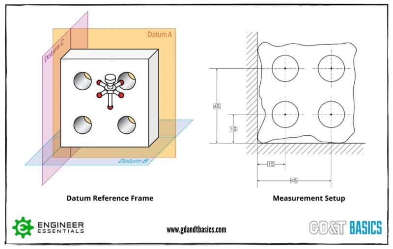
Figure 5: Datum Reference Frame and Measurement Setup
By securing your part to the datums using a datum feature simulator, you are specifying how you want the part to be measured to mimic the actual function of the part. This results in repeatable measurements. In addition to this, you have the ability to inspect the part right on the line by using functional gauging. This can be done when the drawing calls out MMC (Maximum Material Condition) along with Position. We will talk more about using MMC later in our discussion of Bonus Tolerances.
2. Focus on Function
When GD&T is used in a design, the focus is on the function of the part. In the four holed part example given earlier, the goal of the four holes is to attach the part to an assembly using bolts. This is shown below in Figure 6. So, the goal when dimensioning the position of the holes would be to make sure the centers of the holes are not too far away from their targets.
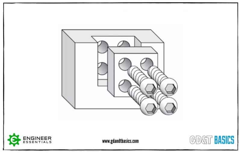
Figure 6: Part Assembly
As you can see in Figure 7, using coordinate dimensions, the shape of the tolerance zone for the position of the center of each hole is a square. Let’s assume that the part was tested, and any hole’s center that fit within the square tolerance zone passed the testing. The worst case that still passed the functional requirement is the furthest measurement from the center – the corner of the square tolerance zone.

Figure 7: Square Tolerance Zone Using Coordinate Dimensioning
But since the holes and bolts are round, should the tolerance zone be limited to a square? If we design with a position tolerance (using the diameter symbol) rather than coordinate tolerances, the tolerance zone is now round instead of a square. You can see this in Figure 8. The distance from the center to the corner point is now the maximum distance all around, rather than only at the four points obtained by the square coordinate tolerance zone. The round and square toleranced parts are functionally the same.

Figure 8: Round Tolerance Zone Using Position Tolerance
A mirror is another great example of how GD&T has the advantage when designing for function. Let’s say that the entire surface of a mirror needs to be flat within 0.2mm to avoid a wavy surface. Without GD&T, you could try to avoid a wavy surface by adding a tight thickness tolerance. However, the thickness could be measured in several places, with each point passing inspection and still have a wavy surface. With GD&T, you can show the intent of the design – a flat surface – by using the flatness symbol, as shown in Figure 9.

Figure 9: Drawing of a Mirror Using GD&T
3. Larger Tolerance Area
We demonstrated earlier that by using GD&T, we can create a round position tolerance zone for the centers of the holes that is functionally the same as the square tolerance zone produced using coordinate dimensions. How does having a round tolerance zone benefit manufacturing?
Figure 10 shows the tolerance area for the square and round tolerance zones of the 4 holed part we have been discussing. In this example, the coordinate dimensions for the location of the center of each hole result in a square tolerance zone with an area of 0.01. (Refer back to Figures 3 and 4 for the Coordinate Dimensioned and GD&T drawings of this part.) To create a round position tolerance zone with the same function as the square zone, we need to create a circle that encloses the square.
To do this, we first need to determine the distance from point to point across the center of the square tolerance zone. This will be our circle’s diameter. You find this using the Pythagorean theorem (a^2+b^2=c^2). This results in a diameter of 0.141. We can then use this diameter to solve for the circular area, resulting in a value of 0.0156.
When we compare the tolerance area of the square and round zones, we see that the round tolerance zone is 56% larger. Having a larger positional tolerance zone means that there are additional points where the center of the hole in the manufactured part could land and still be within the drawing specification. This results in a part that is easier and cheaper to produce!
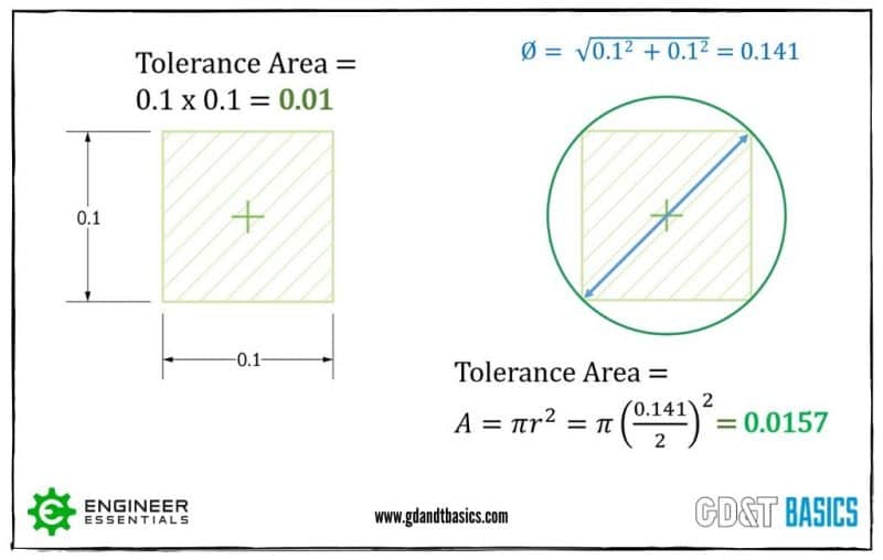
Figure 10: Tolerance Zone Areas
4. Bonus Tolerance
In addition to GD&T allowing for a larger tolerance area, you also get a “bonus tolerance” when a feature is designed for maximum material condition (MMC). Maximum material condition exists when a feature contains the largest amount of material allowed by its size tolerance. A pin would be at MMC when it is at its largest allowable size. A hole is at MMC when it is at its smallest allowable size.
When you are designing mating features, not only do you need to take into account the MMC, but you also need to consider the position tolerance. You do this by calculating the Virtual Condition (VC). Virtual Condition is the worst-case condition that will still allow the mating part to fit. It is the combination of the MMC size and the stated position tolerance at MMC that will allow the parts to assemble.
In the example shown in Figure 11, the virtual condition for the hole at MMC is the minimum inner boundary. To ensure that a pin will fit within this hole, you would design the pin to be smaller than the VC of the hole. To find the VC of the hole, you would subtract the position tolerance from the MMC (smallest hole size).
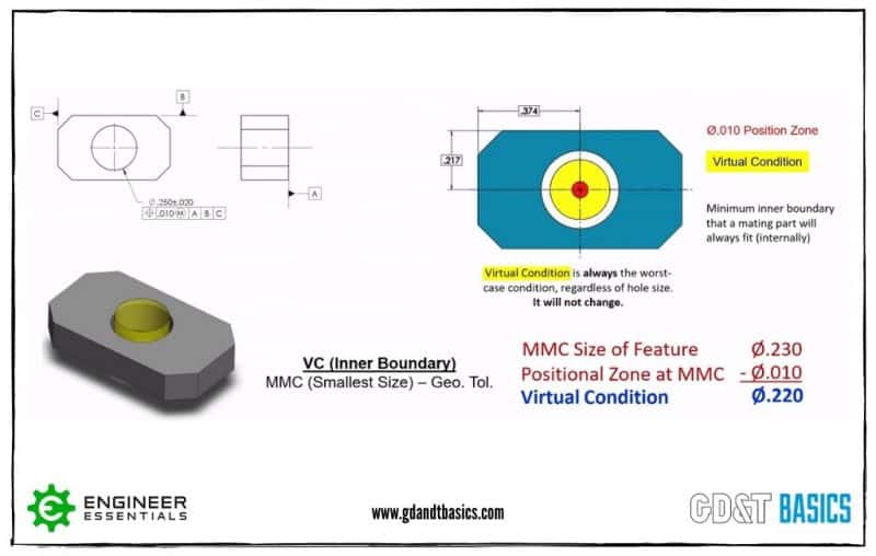
Figure 11: Virtual Condition of a Hole
Now, here is where we get into Bonus Tolerance. Virtual Condition is the worst-case scenario, calculated using the smallest hole size. Figure 12 shows the effects when a hole deviates from MMC (gets larger). The Virtual Condition is shown as a yellow circle and the position tolerance is shown in red. The Virtual Condition never changes. As the hole size gets larger there is more room for deviation in position. So, as the hole size gets larger, you gain bonus positional tolerance.
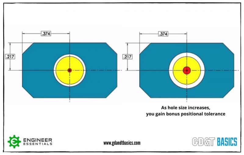
Figure 12: Bonus Tolerance for a Hole
For an external feature, the virtual condition is controlling the outer boundary. The virtual condition is found by taking the pin size at MMC (largest size) and adding the position tolerance to that. The hole that this pin would need to fit into must be larger than the VC of the pin. Figure 13 shows the same type of part as Figure 11, except it has an external feature (pin) rather than an internal feature (hole). In this case, as the pin size decreases (becomes smaller than MMC), the pin gains a bonus positional tolerance, as shown in Figure 13.
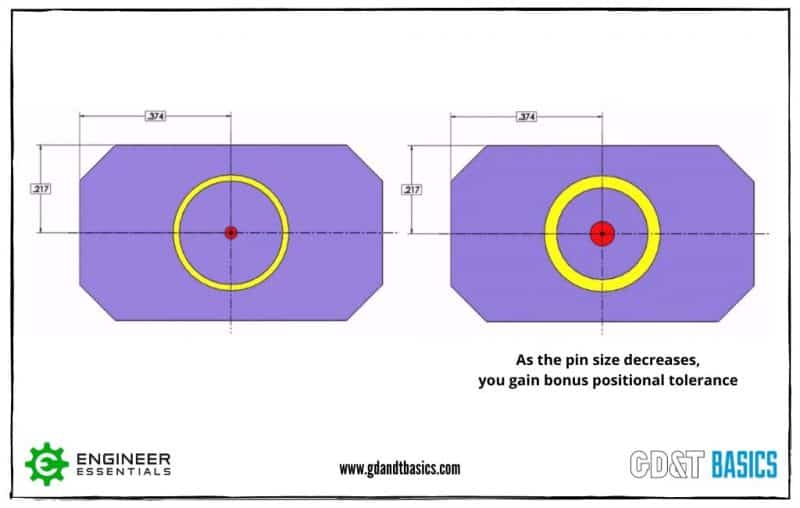
Figure 13: Bonus Tolerance for a Pin
For a more detailed explanation of Bonus Tolerance, check out our video on Maximum Material Condition.
We have covered four advantages of GD&T vs. Coordinate Tolerancing in this article. If you are looking to learn more about Geometric Dimensioning and Tolerancing, and how it is applied in the real world, check out the GD&T Basics Fundamentals course.
In this Fundamentals course, we don’t throw every concept at you – just the topics that are practical for real work with engineering drawings, making this the most practical and productive GD&T course you will find!
If you are interested in learning more about GD&T?
Check out the GD&T Basics Fundamentals course
Click here for information