
Today’s question line video is in response to a student’s question about controlling multiple profiles. The question we received was, “If I have, for example, a plate with 2 identical star shaped cutouts on it, could I just call out 2X profile on one of the shapes?”
To answer this question, Jason reviews a drawing with 2 irregularly shaped identical cutouts in the video below:
In the example below, we see a drawing of a plate with two identical “U” shaped cutouts. Notice that the feature control frame for the cutout on the right side has a multiplier of 2X in front of it. The short answer to the student’s question is, “Yes!” You can identify two identically shaped cutouts with one profile of the surface callout if you put a 2X multiplier in front of the feature control frame. Below, we will walk through the feature control frame to see what it is controlling and how it is controlling the profiles.
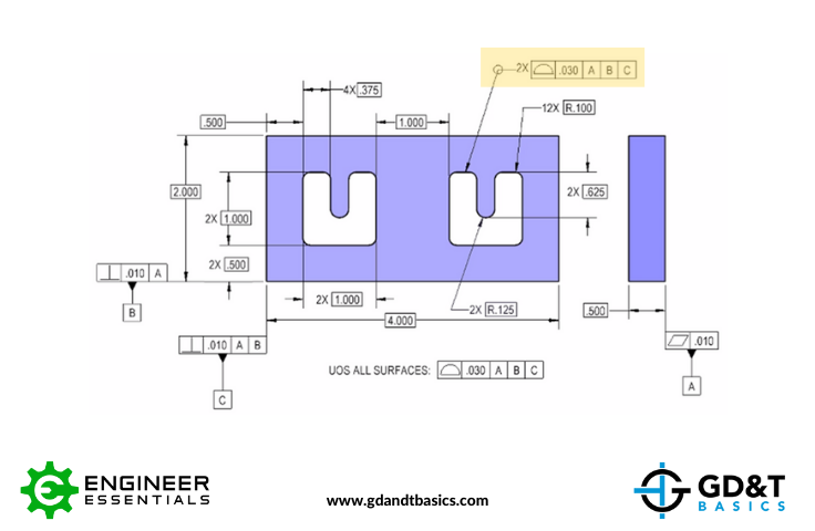
Figure 1: Drawing with Control on Two Profiles
Let’s read the feature control frame for the cutout. First, we see the “all-around” circle on the elbow of the leader line. This tells us that we are going to analyze this pattern of surfaces (straights and curves of the U shape) continuously. Now, reading the feature control frame from left to right, we see that there will be two patterns of surfaces (indicated by the 2X multiplier) held with profile of a surface to a total tolerance value of .030 with respect to datum features A, B, and C.
This means that we have a tolerance of .030 distributed equally about the true profile, which is defined by the basic dimensions. As long as the surfaces do not deviate outside of this tolerance zone, the pattern of surfaces passes profile. This is illustrated in Figure 2, below. It is also important to note that because of the 2X multiplier, there will be two measurements recorded on the inspection report – one reported deviation for the cutout on the left, and one for the cutout on the right.
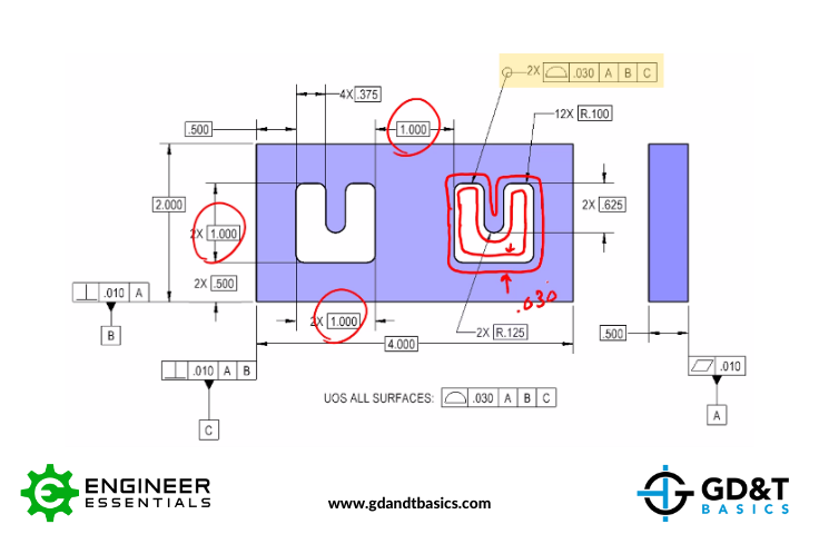
Figure 2: Tolerance Distributed about the True Profile
We also need to remember that these surfaces are located and oriented back to datums A, B, and C. For example, the bottom of the U shape will be perpendicular to Datum A (the back surface of the part) and be .500” away from datum plane B. Though there’s nothing about this specific surface to be located with respect to datum C, other surfaces can be, such as the left surface of the U shape. This is illustrated in Figure 3.
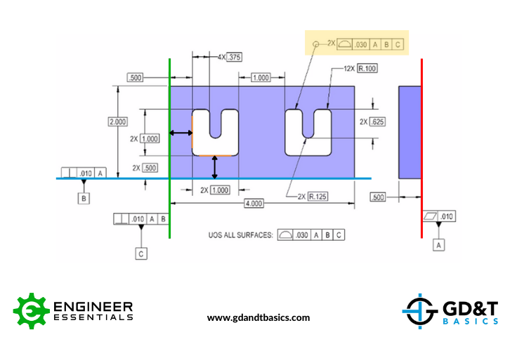
Figure 3: Controlling the Surfaces with Respect to the Datum Reference Frame
Summary
In summary, identical irregularly shaped surfaces can be identified with one profile of the surface callout when a multiplier is used in front of the feature control frame.
The one-page GD&T reference that you will use every day
A visual breakdown of every core GD&T symbol and what it controls, all on one page. Bookmark it. Print it. Actually use it.
Download the Chart