

Are you unknowingly falling into the trap of common GD&T errors in your designs? In this 4-part video series, our Training Design Engineer and resident GD&T guru, Jason, will explore the most common errors that we see in implementing GD&T on engineering prints, and provide you with practical solutions to avoiding these pitfalls. Whether you are an engineer, designer, or drafting professional, this series aims to enhance your understanding of GD&T and help you produce accurate and effective drawings.
In this series, we will cover these common drawing mistakes and how to correct them:
Part 1: Neglecting to Reference the GD&T Standard
Part 2: Common Errors in Defining Features
Part 3: Misuse of the Symmetry Symbol
Part 4: Incorrect Usage of the MMC Modifier
Part 1: Neglecting to Reference the GD&T Standard
A very common issue that we see on GD&T drawings is the failure to indicate which GD&T standard is being applied. In this video, Jason highlights the importance of indicating the standard being used and how to properly reference it on a drawing.
There are many GD&T standards, but the two most commonly used are published by the American Society of Mechanical Engineers (ASME) and by the International Organization for Standardization (ISO). Though they are similar, they have some major differences, so it is important that your drawing references which standard is being used. (For more information see “A Comparison of GD&T Standards: ISO GPS vs. ASME Y14.5.”)
There are several ways that a GD&T standard can be referenced on a drawing. For example, it can be called out in the title block or notes, or it can be indicated in the internal standards that are referenced on your drawing. Below is one example of ISO and ASME standards callouts on a drawing.
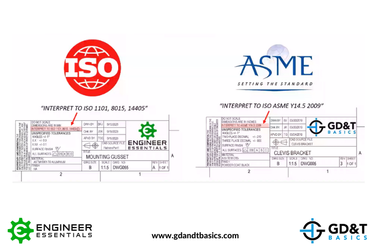
Some common ISO standards referenced on drawings include ISO 1101, ISO 8015, and ISO 14405.
- ISO 1101: Geometrical Product Specifications (GPS) – Geometrical tolerancing – tolerances of form, orientation, location and run-out
- ISO 8015: Geometrical Product Specifications (GPS) – Fundamentals – concepts, principles, and rules
- ISO 14405: Geometrical Product Specifications (GPS) – dimensional tolerancing linear sizes
(This standard is usually paired with the envelope symbol, as shown in the example above.)
For ASME, we usually only see ASME Y14.5 called out on the drawing. However, you must also include the revision year of the standard on your drawing, since the updates to the standard can have an impact on your design. The most used ASME standards are the 1994, 2009, and 2018 versions. You can learn more about the latest ASME standard updates in our ASME Y14.5 2009 vs. 2018 article.
Communicating the GD&T standard on your drawing is vital to ensuring effective communication and adherence to the required specification in the design and manufacturing process.
Part 2: Common Errors in Defining Features
When it comes to Geometric Dimensioning and Tolerancing, it is essential to define features accurately on our drawings to ensure clarity and consistency in the manufacturing and inspection processes. In this video, Jason addresses the common errors he sees when defining features and how to correct them.
We are going to look at the drawing below to showcase several issues that we commonly see in defining features.
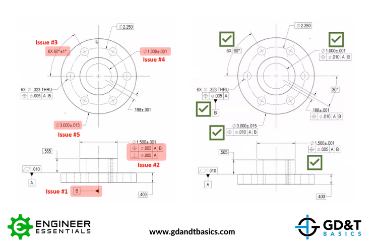
Issue #1: Indicating an axis as a datum feature
In this drawing, the center axis is identified as Datum Feature B. However, notice that there are multiple center axes – an axis for the outside diameter, bolt hole pattern, stepped diameter and inner diameter. Because of orientation and form error, these features will always have some level of error in their coaxiality (even if very small), and this drawing is unclear about which axis is being identified. More importantly, by definition, an axis cannot be a datum feature. A datum feature must be a surface or feature of size from which a datum is derived.
Issue #1 Fix: Select the pattern of holes to be Datum Feature B. The resulting datum is the center axis of the pattern of holes. (More information on a pattern of holes as a datum feature can be found in this article.)
Issue #2: Redundantly defining controls
Notice in the above drawing that the composite OD feature control frame includes a perpendicularity control of .005 in addition to a position control of .005. The position control is already controlling the orientation error to .005 as well as the location error. Adding the .005 perpendicularity control is redundant.
Issue #2 Fix: This fix is very simple – we only need to remove the perpendicularity control from the feature control frame. However, if we wanted a tighter control on perpendicularity than the .005 that we have from the position control, we could refine the orientation by including the perpendicularity control as shown in the first drawing, but with a smaller tolerance.
Issue #3: Over-defining tolerances
We have a pattern of six holes being controlled by a position tolerance of .005 inches with respect to datums A & B, meaning that each of the six holes can radially deviate .0025 from their true position or .005 diametrically. However, we also have an angular dimension of 60° with a +/-1° tolerance. This angular tolerance is competing with the position tolerance, and is over defining the position of the holes. The supplier of this part would not know which tolerance to use in this case and the drawing would violate the GD&T standard.
Issue #3 Fix: Change the angular tolerance to a basic dimension of 60° to allow the position tolerance to control the location. (True position must be defined by basic dimensions.)
Issues 4 & 5: Underdefined features
Both the OD and the ID of the part have size dimensions only. As the drawing is shown, we do not know how far their diameter axes are allowed to drift from the datum axis. These would be untoleranced features and they both need positional control (even if it’s a large tolerance).
Issue 4 & 5 Fix: Add position tolerances to each of the size dimensions. To determine the allowable position error, the designer needs to perform a tolerance analysis to ensure things like minimum clearance are met.
Part 3: Misuse of the Symmetry Symbol
Misuse of the symmetry symbol is a common mistake that we see on GD&T drawings. In this video, Jason sorts out the confusion around the symmetry symbol and when it should be used.
A common misconception is that symmetric features should utilize the symmetry symbol when trying to mirror a pattern. We see this in the drawing below, where the symmetry symbol is used for both the pattern of tapped holes and the pattern of thru of holes.
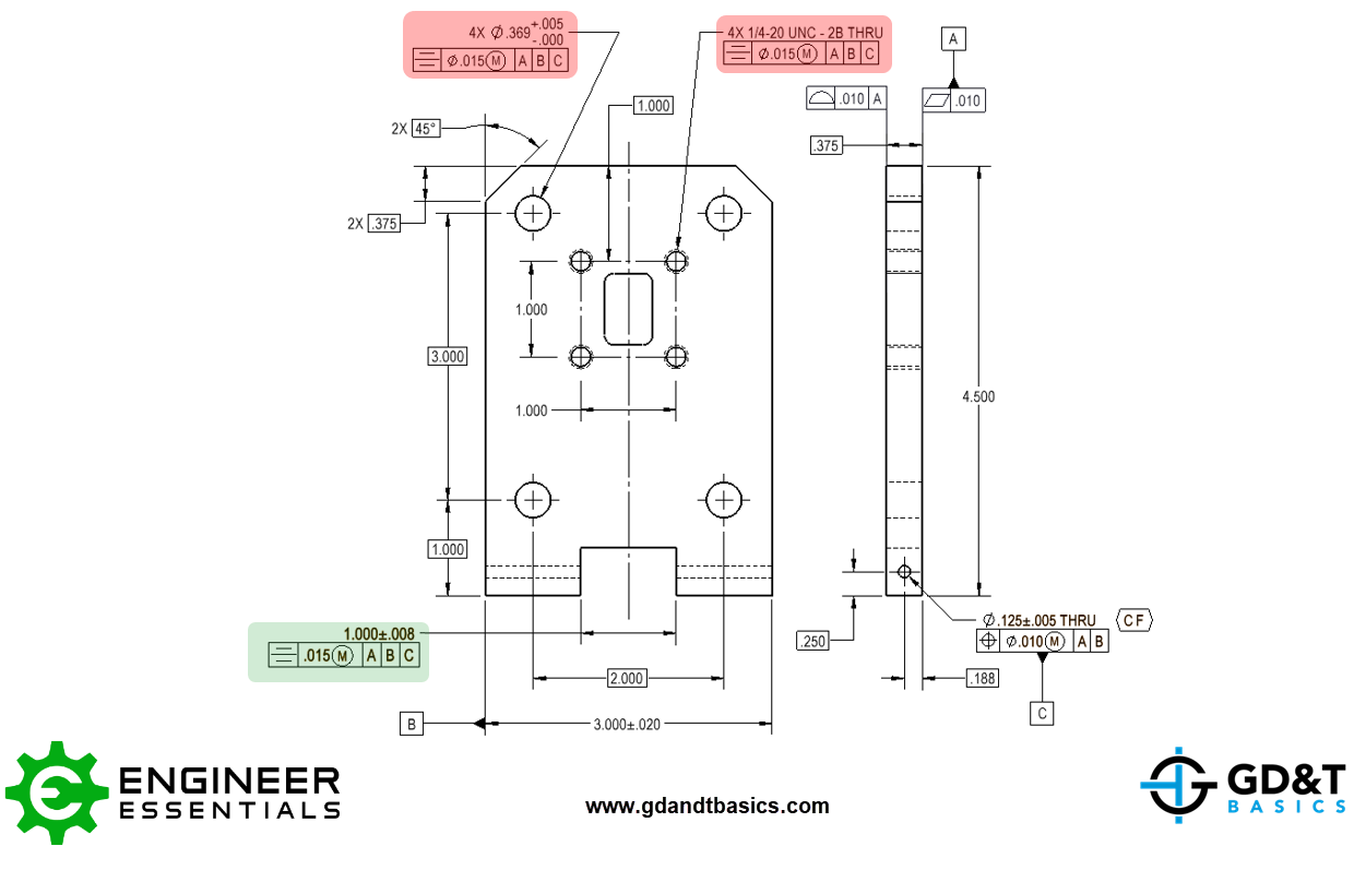
Though both patterns of holes are symmetric about Datum Plane B, the symmetry symbol is not used to define patterns. Symmetry in the ASME standard refers to the diametric location of any derived median elements typically on two symmetric surfaces. The correct use of symmetry is shown for the width feature in the drawing above.
For the width feature in this drawing, the midplane of the feature is coplanar with the midplane of the datum feature. For symmetry to be in tolerance, the median distance between every point on the two surface features needs to fall within the tolerance zone centered on that central datum plane.
However, we still do not advise using the Symmetry control as it is not usually the design intent for the feature. As you can see in the figure below, this notch can be wider at the top vs the bottom, and because the amount of error for elements across from each other are equal, there would be no reported Symmetry error.
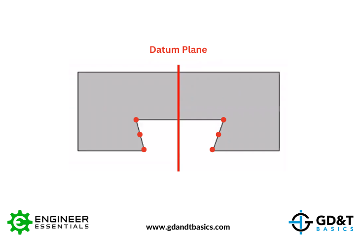
Instead of using a symmetry control, it is recommended to use the position control. Position can control the coplanarity of the datum plane and the midplane of the width feature. Likewise, position will control the location of the holes for the hole pattern, so you can use position to ensure that your pattern stays symmetric.
It is important to note that symmetry has been removed from ASME Y14.5 2018. However, ISO interprets symmetry differently from ASME – as a subcategory of position. You could swap symmetry with position when using ISO standards and it would mean the same thing.
Part 4: Incorrect usage of the MMC modifier
The MMC (Maximum Material Condition) modifier in GD&T drawings is used to allow for bonus position tolerance dependent on the size of the feature. In this final video, Jason addresses the overuse and incorrect usage of the MMC modifier.
The MMC modifier allows for bonus position tolerance, equal to the difference of the actual feature size from the maximum material condition. It permits a feature to drift more in position, if the size tolerance has room, while maintaining the part’s functionality. In the drawing below, we see two instances of the MMC modifier being unnecessarily or incorrectly used.
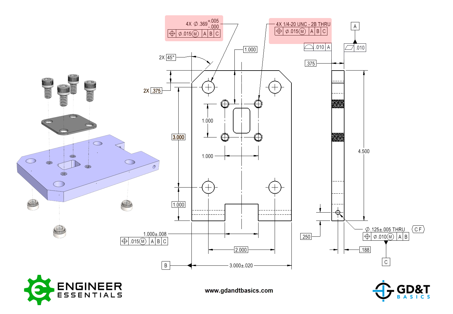
Instance #1: Threaded features
We often see the MMC modifier overused by applying it to threaded features. To determine bonus position tolerance, you must be able to measure the actual feature size. Per ASME Y14.5, when controlling a threaded feature, we are concerned with the size and location of the pitch cylinder diameter. This is very difficult to inspect – in most cases, a go/no-go thread gage is used to ensure the thread profile meets specification, and no actual size is measured. Without the ability to measure the actual size, we cannot determine how much bonus tolerance is allowed, so we get no benefit from including the MMC modifier in the feature control frame. Also – a design does not benefit from a thread being “looser” – there would be no extra clearance on fastener going into the thread.
Instance #2: Interference fit features
We also see the MMC modifier being misused when applying it to press fit holes or any situation requiring a tight tolerance. In these situations, we know that the size dimension will ensure some sort of interference fit. The position error is then calculated using the fixed fastener formula to ensure that once the insert is pressed in, the part will function properly. You don’t want more position error based off of size in this scenario. This isn’t a clearance situation of something going through the hole, we’re worried about the position of what is press fit into the hole.
Conclusion
In conclusion, by exploring these common GD&T errors and their solutions in this four-part video series, we hope to have empowered you with the knowledge necessary to avoid these pitfalls in your designs. The importance of accurately applying GD&T cannot be overstated, as it directly impacts the manufacturing process and the ultimate functionality of the product.
To further support your GD&T journey, we invite you to download our GD&T Symbols Reference Chart. This comprehensive chart serves as a valuable “cheat sheet,” providing you with quick access to all 14 GD&T symbols and their meanings as they appear on engineering drawings. Don’t miss out on this essential resource – click the link below to download the chart and take your GD&T knowledge to the next level.
https://www.gdandtbasics.com/gdt-symbols-chart/
The one-page GD&T reference that you will use every day
A visual breakdown of every core GD&T symbol and what it controls, all on one page. Bookmark it. Print it. Actually use it.
Download the Chart