
We get a lot of questions from students asking why they would want to use Geometric Dimensioning and Tolerancing (GD&T) over coordinate dimensions. Some believe that using GD&T will result in tighter tolerances and increase a part’s cost. Others believe that coordinate dimensioning is just easier to understand, and that it can do everything that GD&T can do. In this article, we are going to show you why these assumptions are incorrect, and how GD&T is the better choice.
Geometric Dimensioning and Tolerancing is a set of rules and symbols used on a drawing to communicate the intent of the design. The core purpose of GD&T is to make sure that the part functions properly. With focus being on the function of the part, GD&T allows for larger tolerances for less important design features, which results in a cost savings for manufacturing.
Let’s look at a bicycle wheel as an example.
We all know that the rounder a bicycle wheel is, the smoother the ride will be. A wheel’s roundness, or amount of up and down movement as it spins, is its radial trueness. As a general guideline, 1 mm or less of radial deviation is acceptable. So how should this be defined on a drawing?
If you were to use coordinate dimensions, you would list the nominal dimension for the diameter of the rim, plus a tolerance range, as shown in Figure 1. Because of the small amount of radial deviation that is acceptable, the tolerance on the wheel rim diameter would have to be pretty tight.
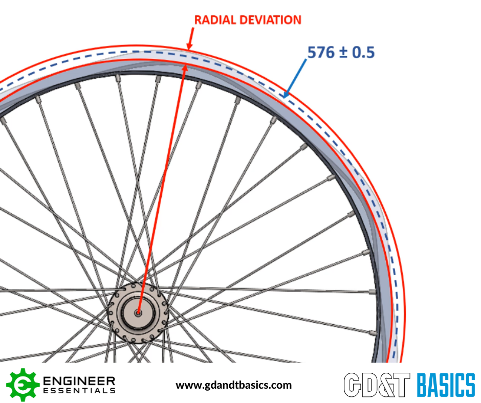
Figure 1: Coordinate dimensions require tight tolerances to control deviation
But wait – what locates the center of this diameter? How far off the center can it be? Also, does it make sense to have such a tight tolerance on the size of the rim, when the manufacturer has a diameter tolerance for the mating tire at 5mm? All of these questions can be answered by using Geometric Dimensioning and Tolerancing. With GD&T, we can both loosen the tolerance of the diameter (size) of the rim while still controlling the required maximum radial deviation of 1mm (form). This radial deviation is controlled through GD&T by using the runout control, which controls location and form. As shown in Figure 2, the tolerance on the size of the diameter of the rim has been opened up to +/- 1.25mm. The radial deviation is being controlled using the feature control frame (shown below the rim diameter dimension). In this feature control frame, the runout symbol is shown in the left box, with the tolerance dimension (1mm) in the center box, and the datum reference (A) in the box on the right. Datum A being the central axis of the rim.
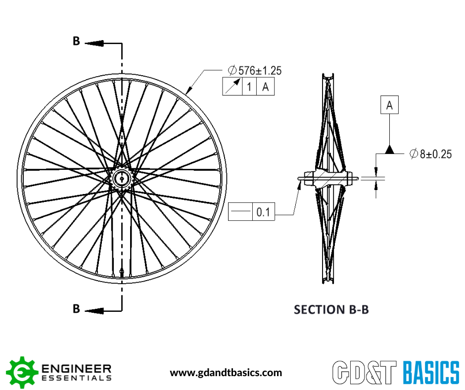
Figure 2: GD&T allows for loosened tolerances while controlling form using runout
In order to ensure this wheel meets the functional requirements, runout would be checked against the datum created by the axle diameter (Datum A). This is done by locking the tire’s axle into a truing stand. This truing stand becomes the datum simulator for Datum A in the drawing. The tire can then be rotated to check the radial deviation with respect to that center axis.
As you can see, using GD&T allows us to meet the functional requirements of a part without adding unnecessary tight restrictions, thus saving manufacturing costs. For a more in-depth look into why you should use GD&T, check out the video below.
The one-page GD&T reference that you will use every day
A visual breakdown of every core GD&T symbol and what it controls, all on one page. Bookmark it. Print it. Actually use it.
Download the Chart