
What is GD&T? If you are involved in design or manufacturing, you may be familiar with the term, “GD&T,” or “Geometric Dimensioning and Tolerancing”. Geometric Dimensioning and Tolerancing is a set of rules and GD&T symbols used on a drawing to communicate the intent of a design, focusing on the function of the part. Using GD&T results in a more accurate design, larger tolerances for less important design features, and cost savings for manufacturing.
History of GD&T
How did GD&T come about? Near the beginning of World War II, a man named Stanley Parker was working at the Royal Torpedo Factory in Alexandria, West Dunbartonshire, Scotland. Parker realized that there were parts that met functional requirements that were being rejected due to out of tolerance measurements. He went on to develop tolerancing practices to address the functional requirements of a part. Parker published the first work on GD&T in 1940, titled, “Notes on Design and Inspection of Mass Production Engineering Work.” He published another title in 1956, “Drawings and Dimensions.” Parker developed the concept of “True Position” and is credited with being the originator of GD&T.
The first standards for GD&T were developed by the US military in the 1940s. MIL-STD-8 was published in 1949, and was revised in 1953 to include GD&T “Rule 1.” Then in 1957, the American Society of Mechanical Engineers (ASME) published their first standard incorporating GD&T, ASA Y14.5. The ASME Y14.5 standard has been revised approximately every 10 years to address new concepts and new technology, with the most recent revision released in 2018. Another popular set of GD&T standards in use worldwide has been published by the International Organization for Standardization (ISO). In 1996, the ISO Technical Committee 213 was formed to create and maintain ISO Geometrical Product Specifications (GPS). For a comparison of ASME and ISO GD&T standards and their usage, check out “A Comparison of GD&T Standards: ISO GPS vs. ASME Y14.5.”
Benefits of GD&T
Many companies from a variety of industries are using GD&T. ASME lists several well-known companies that have purchased the GD&T standard, ASME Y14.5, including General Electric, Honeywell, Lockheed Martin, Ford Motor, Eastman Kodak, Hewlett-Packard, and many more.
So, why are so many successful companies using GD&T, rather than simple coordinate dimensioning and tolerancing? GD&T allows the designer to communicate the design intent, and is a focus on the function of the part. By focusing on the function of a part, less important tolerances may be loosened. Loosened tolerances result in a part that is easier and cheaper to produce.
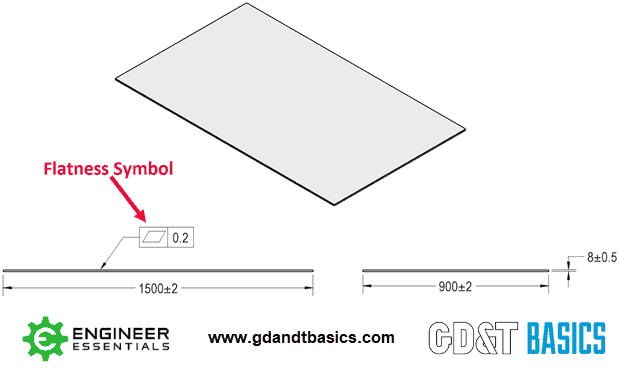
The design of a mirror is a great example of this concept. The intent of the design of a mirror is for it to be flat to prevent a distorted reflection. Using coordinate dimensioning and tolerancing, you could try to avoid a wavy surface by adding a tight thickness tolerance to the drawing. However, the thickness could be measured at several points, each point passing inspection, and the mirror still have a wavy surface. This situation is prevented using GD&T. As seen in Figure 1, a flatness symbol would be used to show the intent of the design. By focusing on the function and indicating the desired form (a flat surface), the thickness tolerance could be loosened, resulting in a part that meets the function requirements and is easier to produce.
For more information on the advantages using of GD&T, including benefits to inspection and an in-depth discussion of tolerance, see “Advantages of GD&T vs. Coordinate Tolerancing.”
Basics of GD&T
As mentioned previously, Geometric Dimensioning and Tolerancing is used to show the intent of a design that coordinate dimensioning and tolerances alone do not show. This is done by considering SLOF when creating the design, and by applying geometric controls to the drawing.
What is SLOF? There are four components to making sure that your drawing indicates the geometric and size requirements of each feature. These four requirements are known as SLOF: size, location, orientation, and form.
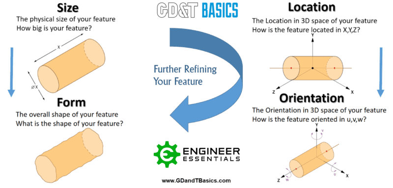
Size refers to the physical size of a feature. This is usually controlled by the normal ± tolerancing you are used to seeing, although Profile can also control size.
Location is the location of the feature in 3D space, relative to other features. Most commonly Position is used for this type of control.
Orientation is how your part is angled, or oriented in 3D space, relative to other features. Orientation symbols are used as a further refinement of location. Commonly, Parallelism, Perpendicularity, and Angularity are used to control these. Although many other symbols also will indirectly control the orientation, such as Runout.
Finally, Form refers to the overall shape of the feature. Form symbols, such as straightness, flatness, circularity, and cylindricity, are final refinements and are only used when functionally necessary.
For the best free GD&T guide and a comprehensive overview of each callout – visit our GD&T symbols page.
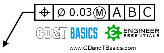
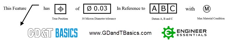
To apply the geometric controls to a feature on a GD&T drawing, a feature control frame is used. A feature control frame includes four pieces of information – the GD&T symbol, the tolerance zone type and dimensions, tolerance zone modifiers, and datum references (when required).
Figure 3 is an example of a feature control frame, and Figure 4 shows how this feature control frame would be read.
Meeting all four SLOF components and properly applying geometric controls to your drawing will ensure that your part can be produced accurately and consistently.
Where to Learn More
If you are looking for more information on GD&T, you’re in the right place. GD&T Basics is the #1 free online resource for Geometric Dimensioning and Tolerancing training. In addition to our different training programs and courses, we offer tons of free resources.
Register today for your Free GD&T Wall Chart and receive exclusive training videos, weekly industry insights, and other helpful tips. You can also visit our blog for best practices, helpful explanations, and simple advice for using GD&T in the real world.
Want to get more GD&T training for free?
Download our free GD&T symbols chart when you subscribe to our weekly email newsletter.
GET MY FREE CHART