

Jason explains how to tell at a glance whether a drawing has inch or metric dimensions in the Question Line video below.
We received the following question from a student through our Question Line, “How can I tell if my drawing is in inches or millimeters if it’s not listed on the drawing?” This question comes up frequently in our courses when we are using zoomed in views of a drawing, where the title block of the drawing is not shown.
If the designer of the drawing is following the rules, it is easy to tell at a glance whether the drawing has inch or metric dimensions. So, what are these rules?
Rules for drawings dimensioned in inches:
- Trailing zeros must be added so that a dimension and its tolerances have the same number of decimal places.
- No leading zeros are added for values less than 1.
Rules for drawings with metric dimensions:
- No trailing zeros are added except for the case of a non-zero, non-symmetric tolerance.
- Leading zeros are added for values less than 1.
Drawing Examples
Let’s look at a couple of drawings to see these rules in action.
In Figure 1, we have a drawing dimensioned in inches. Notice that the outer diameter of the circular part is dimensioned as “1.00 +.00/-.01”. The tolerance for this dimension has two decimal places, therefore, according to the “trailing zeros” rule, the nominal dimension must also have two decimal places to match that of its tolerance.
Now let’s look at the inner diameter of the circular part. The ID for this part is less than one inch. Due to the “no leading zeros” rule for inch drawings, the nominal ID is written as “.75” with no zero in front of it.
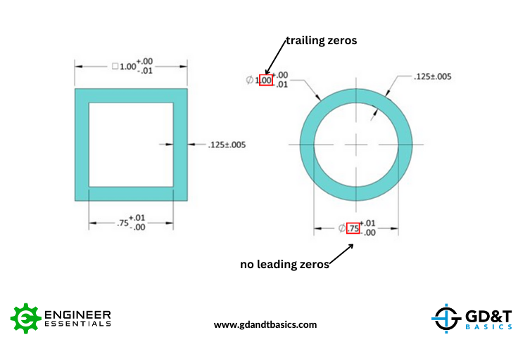
Figure 1: Drawing Dimensioned in Inches
Figure 2 shows the same parts dimensioned in millimeters. The inner dimension for the square shows a tolerance of “+0.25/-0”. According to the “no trailing zeros” rule, the lower tolerance does not have trailing zeros to match the number of decimal places of the upper tolerance, because the lower tolerance is zero. When we look at the inner diameter of the circle (19.05 +0.25/-0.10), we see that the lower tolerance does have a trailing zero to match the number of decimal places of the upper tolerance. This is the exception to the “no trailing zeros” rule – because the upper and lower tolerances are non-symmetric, and the lower tolerance is less than one, a trailing zero was added to the lower tolerance to match the upper tolerance.
Also, see how the “leading zeros” rule was followed for the circular part. All of the tolerances are less than zero, so they all have a zero before the decimal point.
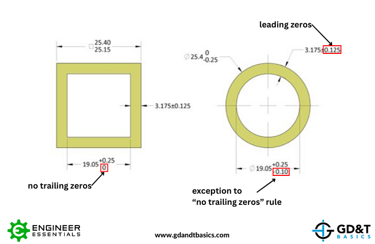
Figure 2: Drawing Dimensioned in Millimeters
As you can see, if drawing rules are properly followed, it is easy to quickly determine whether a drawing is dimensioned in inch or metric units by looking for leading and trailing zeros. However, in the real world, it is best not to assume rules are being followed and to confirm the drawing units.
The one-page GD&T reference that you will use every day
A visual breakdown of every core GD&T symbol and what it controls, all on one page. Bookmark it. Print it. Actually use it.
Download the Chart