Category: GD&T Symbol Rules and Examples
Articles related to GD&T symbol rules and walk-through examples of GD&T Symbols and their uses

Indicates a tolerance or dimension applies to multiple identical features. Simplifies drawings by replacing repetitive callouts with a single note.
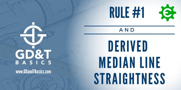
"Why doesn’t Rule #1 apply to the straightness of a Derived Median Line?" In this article, we look at both surface straightness and straightness of a feature of size to understand why Derived Median Line Straightness overrules Rule #1 of GD&T.

Defines the rate of change of a flat tapered surface. Used on flat features the same way conical taper is used on round ones.

Defines the ratio of diameter change to length along a conical surface. Gives a clear, single-value callout instead of two separate angle dimensions.

Indicates a dimension is measured along an arc, not as a straight chord. Used when the curved length — not the straight-line distance — is what matters.

Identifies the dividing line on a part where mold halves or die sections meet. More of a manufacturing note than a geometric control.

Shows that a dimension originates from a specific surface, not from the opposite end. Controls interpretation of tolerance stack in one direction.

Indicates the depth of a feature like a hole, slot, or counterbore. Replaces the word 'deep' on drawings — clean, compact, unambiguous.

Controls the diameter of a full spherical feature. The prefix S∅ distinguishes it from a standard diameter callout on a cylinder.

Indicates the dimension is a diameter, not a radius. One of the most common symbols on any drawing with cylindrical features.

A radius with a smooth, fair curve — no flats or reversals allowed within the tolerance zone. Tighter than a standard radius callout.

Applied to a spherical surface to control its radius. Works like a standard radius callout, but in all directions around the sphere.

Indicates a square cross-section with a single dimension. Saves space on drawings when both sides are equal — one callout covers both.

Defines a radius tolerance zone where the curve must fall between two arc boundaries. Allows slight waviness — use controlled radius when that matters.

Specifies the angle and diameter of a countersunk hole. Commonly paired with a depth or diameter dimension for fastener seating.

A very shallow counterbore used to create a clean, flat bearing surface. Common on cast or rough parts where a fastener needs a flat seat.

Specifies a flat-bottomed enlarged hole above a through hole. Controls the diameter and depth needed to seat a bolt head or fastener flush.

Applies a tolerance to the tangent plane of a surface rather than the full surface. Useful when mating contact matters more than overall surface form.

Indicates a measurement taken without restraining the part. Critical for flexible or non-rigid parts that deflect under normal clamping.

Extends the tolerance zone beyond the feature itself — typically above a threaded hole. Controls where a fastener will sit in the mating part, not just the hole.

Treats interrupted surfaces as a single continuous feature under one tolerance. Eliminates the need for separate callouts on each segment.

Defines specific points, lines, or areas that establish a datum — instead of the entire surface. Used when surfaces are too rough or irregular to reference fully.

An ISO-only symbol that requires the actual surface to fit within a perfect form envelope at MMC. Similar in concept to ASME Rule #1, but explicitly called out.

An ISO-only symbol that explicitly removes the envelope requirement from a feature. Allows form to vary independent of size — the opposite of Rule #1.

Requires that a feature of size have perfect form at MMC. It's a default rule in ASME Y14.5 — one every engineer should understand before drawing a size dimension.

Offsets the profile tolerance zone more to one side than the other. Useful when stock removal or coating thickness shifts the functional surface.

There can be a lot of confusion when dealing with circularity – especially when identifying the tolerance zone compared to how Rule #1 of Geometric Dimensioning and Tolerancing controls it. In this video, we provide...
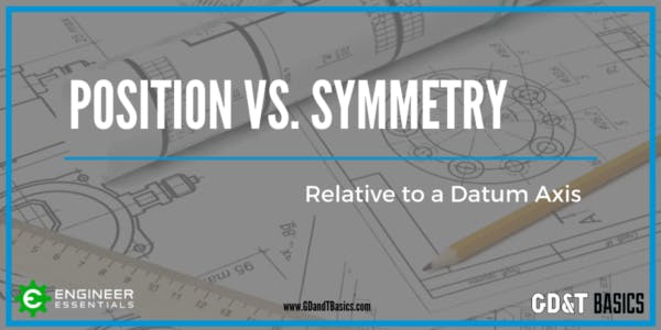
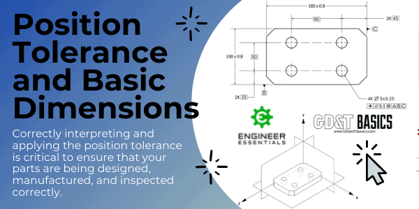
This video is in response to a question that we received on our question line from Alex. His question is as follows: “Is there a best-practice way to use Position (instead of Symmetry) to control...
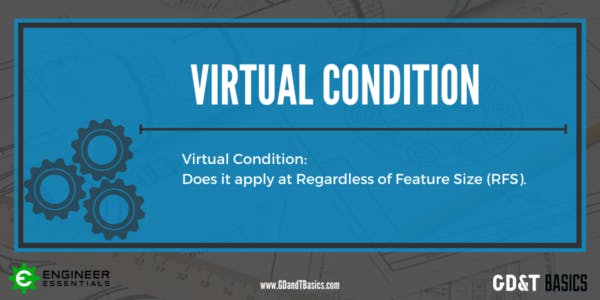
In this question line video, Brandon discusses Virtual Condition and whether it can apply at Regardless of Feature Size (RFS). What is Virtual Condition (VC)? When a feature is controlled with the Maximum Material Condition...
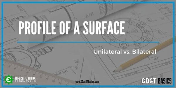
What is the difference between unilateral and bilateral tolerance in a profile of a surface callout? In this post, Brandon explains the difference and gives examples of how they are used. Profile of...
This video is in response to a question that we received on our question line from Amar. Amar’s question is as follows: “If we are given a BASIC radius of 10mm, and on the radius,...

This video is in response to a question that we received on our question line from Tim. Tim’s question is as follows: “We tend to use true position on threaded holes. Is this valid? If...
This video is in response to a question that we received on our question line from Jamee. Jamee’s question is as follows: “For parallelism of a circular feature of size (axis) can you use two...

This video is in response to a question that we received on our question line from Lokesh. Lokesh asked us if a material modifier can be used with cylindricity. Geometric Dimensioning and Tolerancing modifiers are...
This video is in response to a question that we received on our question line from Ignacio. Ignacio asked us if it is a bad practice to reference three datums in a single drawing callout...
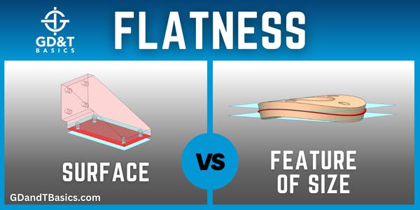
In this video, Brandon discusses the difference between measuring Flatness of a Surface and Flatness of a Feature of Size (FOS). Flatness of a Surface Surface flatness is the type of flatness that most people...
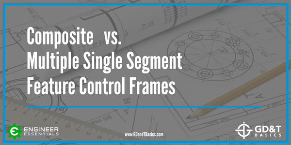
In this video, Brandon compares a Composite Feature Control Frame and a Multiple Single Segment Feature Control Frame to show the effect of each on Position tolerance. What is a Composite Feature Control Frame? A...
The video below is in response to a question that we received on our question line from Ash. The question is as follows: “I regularly see drawings where spacing between a pair of holes is...
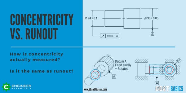
The video below is in response to a question that we received on our question line from Jeff. Jeff asked us if concentricity is always equal to half of the runout value. ASME Y14.5 defines...
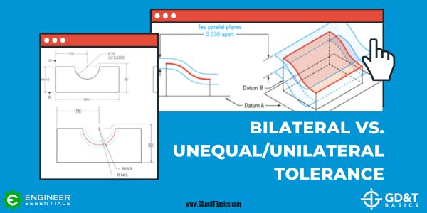
In this article, we explain the differences between bilateral, unilateral, and unequally disposed tolerances. What is a Tolerance? Tolerances on technical drawings communicate the amount of variation permitted from a target dimension. The allowable variation...
