
The video below is in response to a question that we received on our question line from Ash. The question is as follows: “I regularly see drawings where spacing between a pair of holes is critical, but not so much the position of the pair as a whole. Often the dimension to the first hole is a sheet tolerance, and then the spacing between them is basic with a true position indicating the allowable deviation. I don’t believe this to be correct as your first hole is still subject to the looser tolerance, and you are not positioning your second hole from the center of where the first hole falls, but by the dimensions stated. Is my understanding of this right?”
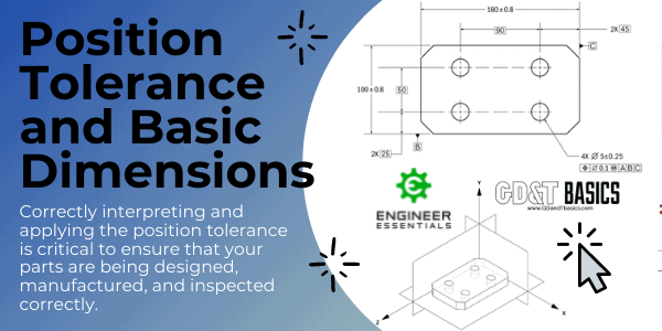
The practice that Ash describes is not correct. When using the position Geometric Dimensioning and Tolerancing callout to locate holes, the position is established from datum references in the feature control frame. Basic dimensions are required to locate the true position relative to datum features, but a +/- tolerance cannot be applied to these basic dimensions. The basic dimensions are considered theoretically exact locations. Once the true position is located relative to the datums, the diameter symbol in the feature control frame tells us that the position tolerance zone is cylindrical. The size of the tolerance zone for each hole is dictated by the tolerance stated in the feature control frame.
Sheet tolerance cannot be applied to the basic dimensions that indicate hole position because they would conflict with the true position tolerance and ultimately result in “double” tolerancing.
This concept is illustrated in the video example as follows: The feature control frame for the position tolerance callout references datums A, B, and C. The referenced datums in this position tolerance also define the orientation of the tolerance zones, which is perpendicularity to datum plane A. Basic dimensions are used to locate the pattern of cylindrical tolerance zones from datum plane B, then from datum plane C. Note that these dimensions do not have a +/- tolerance associated with them. The three datum references define the perfect location and orientation of our cylindrical tolerance zone pattern. The example then shows two intersecting planes as the true position of the tolerance zone, which is represented as a blue cylinder, and the hole axis must lie within this.
Note that when inspecting the part, we will locate the holes in relation to the datum reference frames. We will note the actual position of the hole and compare it to the true position to determine if the hole is located within tolerance.
Also, note that the size information for the holes is provided separately as a diameter dimension with a +/- tolerance. This is defined separately from the position tolerance.
We are working on several other videos that will respond to more questions regarding position tolerancing, so stay tuned for more information. Also, our team at GD&T Basics is here to help with all of your questions and training needs.
Sign up for our GD&T Basics Email list for a free sample from our GD&T Fundamentals Course
If you subscribe you will also receive our amazing GD&T wall chart
Join our Mailing List