
In this article, we explain the differences between bilateral, unilateral, and unequally disposed tolerances.
What is a Tolerance?
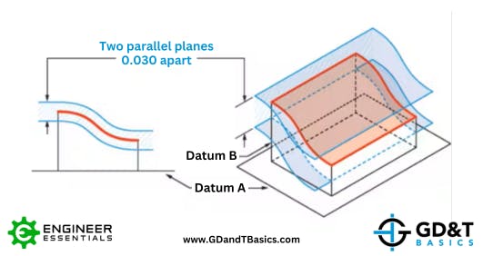
Tolerances on technical drawings communicate the amount of variation permitted from a target dimension. The allowable variation can be visualized as a zone surrounding the ideal surface of the part – what is called “true profile.” For parts to be within tolerance, all points on the surface must fall inside this limit, known as a “tolerance zone.”
Bilateral Tolerance
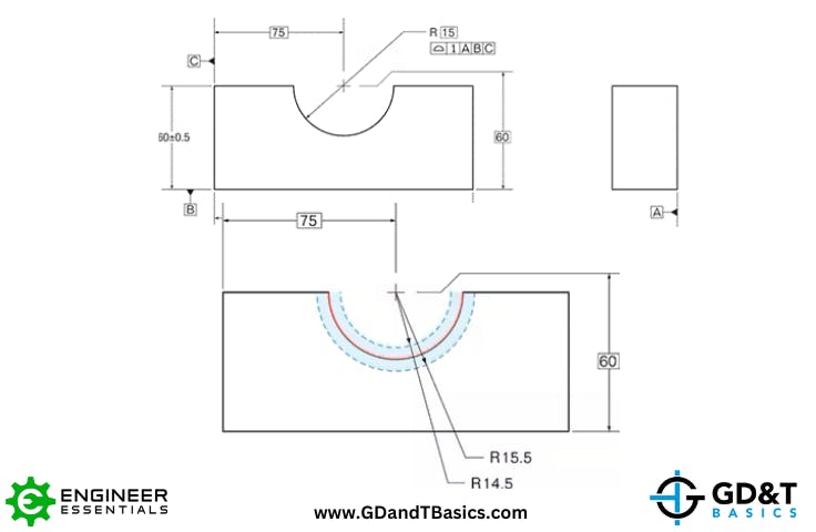
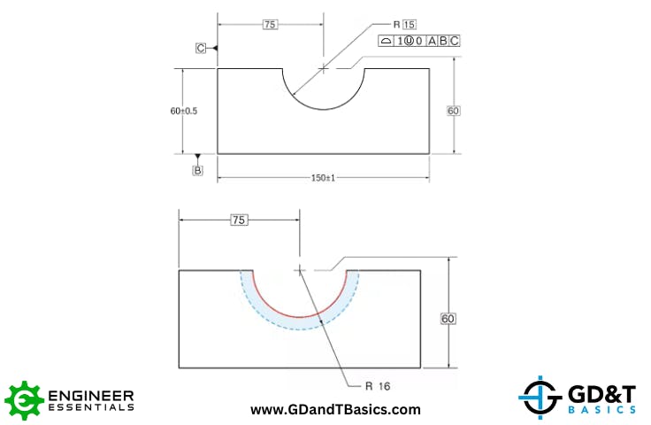
Bilateral tolerance is the term used when the tolerance zone is distributed from the target value or true profile in both directions. Bilateral tolerances allow equal variation on each side of the target. Figure 1 below shows the GD&T notation for profile with a bilateral tolerance of 1mm placed on the 15mm radius. The tolerance zone for this case can be visualized as the space between the two concentric arcs shown in blue. By default, the tolerance is equally disposed about the true profile, meaning that 0.5mm of variation is permitted in each direction from the true profile (15). In this case, the inner blue arc would have a radius of 14.5mm, and the outer arc would have a radius of 15.5mm, and the measured surface of any part would have to fall within this tolerance zone.
Unequally Disposed Tolerance
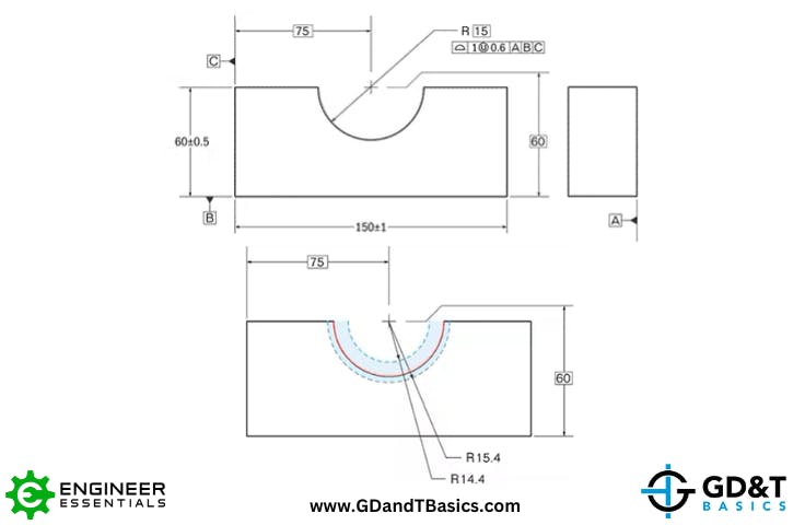
Tolerance zones can also shift to allow variation to be larger on one side of the true profile. This is called unequally disposed tolerance. In Geometric Dimensioning and Tolerancing, unequally disposed tolerance is indicated by an encircled capital letter “U”. The unequally disposed symbol is shown after the total tolerance number in the feature control frame as shown in Figure 2 below. It is followed by a number indicating how far the tolerance zone extends outward from the true profile. This means that the number to the right is “adding material”. Say that we want to modify our example from Figure 1 so that the minimum allowable radius of our arc is 14.4mm. Since the true profile is a perfect arc with a radius of 15mm and we will allow the actual surface to be 0.6mm outside of that, the number “0.6” would follow the “U” symbol as shown in Figure 2 below. In this case, the inner blue arc would have a radius of 14.4mm, and the outer arc would have a radius of 15.4mm.
Unilateral Tolerance
Unilateral tolerance is a type of unequally disposed tolerance where variation from the true profile is only permitted in one direction. GD&T notation for this is identical to unequally disposed tolerance, with the number trailing the “U” symbol either zero or equal to the tolerance amount.
As you may have learned from our GD&T Fundamentals Course or other reference material, it is good practice to design parts at maximum material condition, or MMC. MMC means using the largest possible pin or smallest possible hole within the tolerance zone. Unilateral tolerance allows us to specify tolerances in a way that matches the thought process of our design. Using the same example from Figure 1, we apply this concept to Figure 3 below. We want the MMC size of our radius to be 15mm, which is the basic radius dimension, so we will add “0” to the right of our “U” symbol. This means that the tolerance zone will be distributed to the inside of the feature and cannot get any smaller than 15mm but can get as large as 16mm.
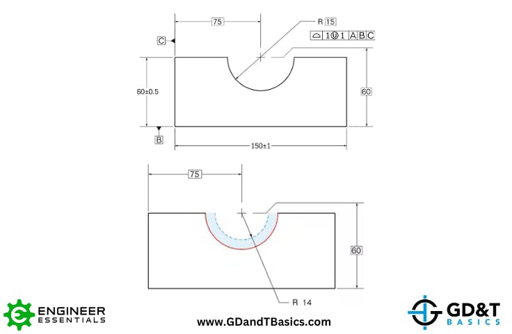
Let’s look at one last scenario. What if we didn’t want the radius to get any larger than 15mm? As shown in Figure 4 below, if we add “1” to the right of the “U” symbol our tolerance zone will only be distributed to the outside of the true profile. Remember what we stated earlier, “the value to the right of the “U” symbol adds material”. Therefore, our radius can never be larger than the basic radius dimension of 15mm, but can get as small as 14mm, which would now be the MMC size.
Another reason for using unilateral tolerances is to shift the statistical variation of parts toward one end of the allowable range. If a manufacturer is making parts to a drawing with an equally disposed bilateral tolerance, we expect the distribution to be centered about the true profile. However, if we find that the parts fit better at MMC, creating a better quality and longer lasting assembly, we could switch the bilateral profile tolerance over to a unilateral profile tolerance to communicate that to the manufacturer.
Key Take-Aways
- Bilateral profile tolerance means variation from the true profile is permitted in equally in both directions.
- Unequally disposed profile tolerance means that more variation from the true profile is permitted in one direction than the other.
- Unilateral profile tolerance means that variation from the true profile is permitted in one direction only.
Check out the video below, which is directly from our GD&T Fundamentals Course. This is a lesson pulled from our Profile Tolerances section on Profile Modifiers – Bilateral, Unilateral, and Unequally Disposed Profile. It reviews the differences between bilateral, unilateral, and unequally disposed tolerances that we explain in this article.
Interested in more lessons from our GD&T Course?
Check out the various Engineering Print and GD&T courses that we have available to help!
View out Online Course Options