In this Question Line video, Jason reviews a drawing example to explain when Maximum Material Condition and Maximum Material Boundary modifiers may be applied.
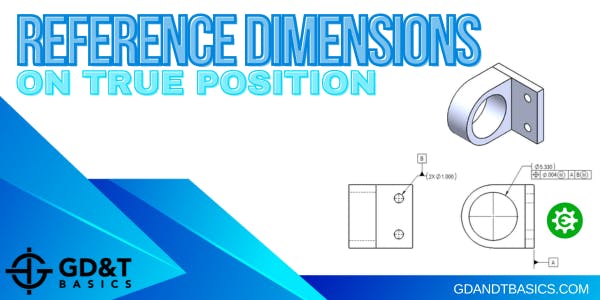
In this Question Line video, Jason walks through an assembly drawing to explain the scenario where a feature being controlled by position must have a reference size dimension rather than a tolerance on the size of the feature.
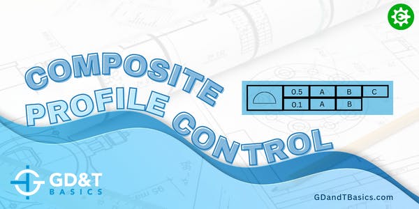
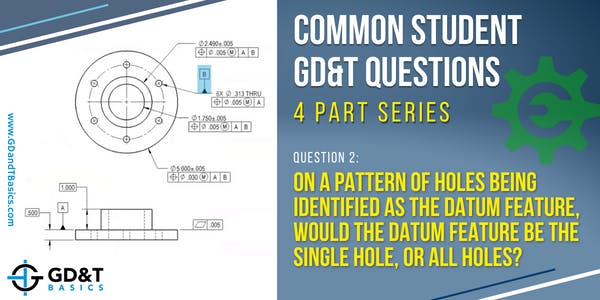
In this Question Line video, Jason discusses a composite feature control frame controlling profile tolerance. He walks through through the user submitted examples to explain the controls of each frame.
In this question line video, Jason explains how to control radial position with a composite tolerance by walking through an example of a pattern of holes on a cylinder.
Geometric Dimensioning and Tolerancing, and the concept of “True Position,” originated due to a rejection of functional parts as a result of coordinate dimensioning. Let’s look at a simple assembly to illustrate why this is true, and how GD&T Position takes care of this problem.
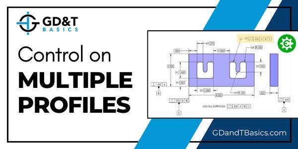
Jason reviews a drawing with two identical cutouts to show whether multiple profiles can be controlled by including a multiplier with the feature control frame.
Can you use the MMC modifier and still ensure a minimum wall thickness? To answer this question, we are going to look at a drawing of a flywheel and compare how using the MMC modifier or the LMC modifier affects the minimum wall thickness.
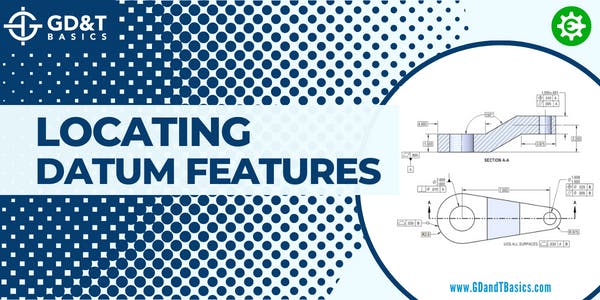
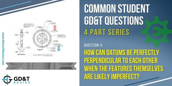
Why doesn't a feature of size that is indicated as a datum feature need to be located? In this article and corresponding question line video, we look at two drawing examples to illustrate why datum features are not located.
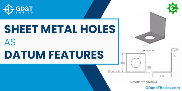
If I specify a hole in a practically thin feature, such as a piece of sheet metal, is this still considered a cylindrical datum? Is this a poor choice of datum? In this article, we look at an example to help us answer these questions.
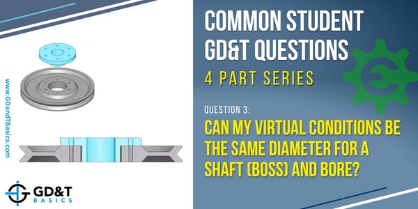
Is it allowable to have identical Virtual Conditions for mating boss and bore features? Watch this video to learn how to calculate and compare Virtual Conditions of mating features.
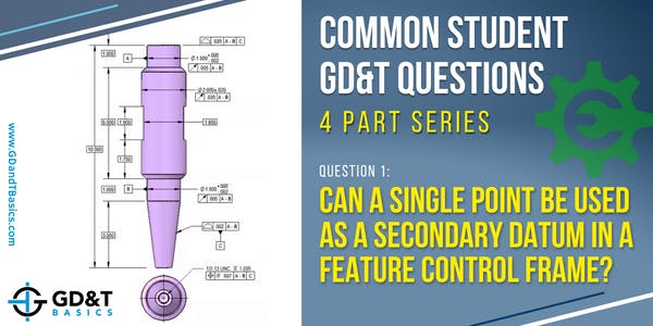
Can a single point (without clocking) be used as a secondary datum in a feature control frame? To answer this question, we first need to determine what datum feature is being represented by this single point. Read on to discover the answer to this commonly asked question from our GD&T students.
When applying position tolerances to countersunk fixed fastener assembly conditions, our design must not only ensure assembly, but also that the fastener head sits flush or below the surface of the part. We are able to determine the values required to achieve this by using the fixed fastener equation.
This 3-part series is great for designers or anyone who may be applying things to an engineering drawing. In this series, we’ll review the top 3 things that manufacturing and quality departments wish you knew...
To determine when to use Profile of a Surface or Coordinate Dimensioning, let’s first look at what the 2009 ASME Y14.5 Geometric Dimensioning and Tolerancing Standard tells us. Paragraph 2.1.1 was revised to emphasize/encourage the...
Properly defining, qualifying, and referencing datum features is essential to ensure that parts are properly manufactured and inspected. To begin exploring proper use of datum features, it is helpful if we first review definitions and...
In this video, we respond to a question asking how using Geometric Dimensioning and Tolerancing can affect internal or vendor-provided manufacturing and inspection processes. It is important to remember that the goal of GD&T is...
There are many great reasons why engineers & designers benefit from knowledge of Geometric Dimensioning & Tolerancing (GD&T). But today, we want to share with you just one reason that is particularly interesting. Even though...
How do you create a quality design, but at the same time, keep cost and ease of production in mind? In this article we will examine three key areas in designing for manufacturability and give...
We would like to shed light on an interesting discussion stemming from a question asked in our Print Reading and Tolerances Course. A student shared their viewpoint about the correct use of centerlines in engineering...
In this question line video, Brandon outlines the pitfalls of Chain Dimensioning and explains how Baseline Dimensioning (or GD&T) can eliminate potentially unwanted tolerance stack. Chain Dimensioning is when dimensions are drawn from one feature...
In this question line video – Tom discusses how to understand a curved profile surface as a datum for 4 holes that are required to remain normal to the irregular surface. How do we do...