
We receive many GD&T questions from our students, and in a recent live instruction webinar, we answered four that are commonly asked. We are now making this available to everyone in a four-part series on our blog and YouTube channel! Today we are answering question number 1:
Question #1: Can a single point (without clocking) be used as a secondary datum in a feature control frame?
Before we answer this question, let’s review the concept of datums and datum features.
Datum features are actual, tangible features on a part and are usually important functional features. Datums are derived from datum features and are theoretically exact points, lines, axes, and planes which are simulated by measurement equipment. Datums are used in Geometric Dimensioning and Tolerancing drawings to create a Datum Reference Frame, the reference system for inspecting a manufactured part.
Now let’s look at specific datum features and their resulting datums:
A Planar Surface as a Datum Feature
A planar surface as a datum feature is the actual irregular surface on a part. The highpoints of the surface will be used to create the datum, which will be a theoretical flat plane that represents that surface.
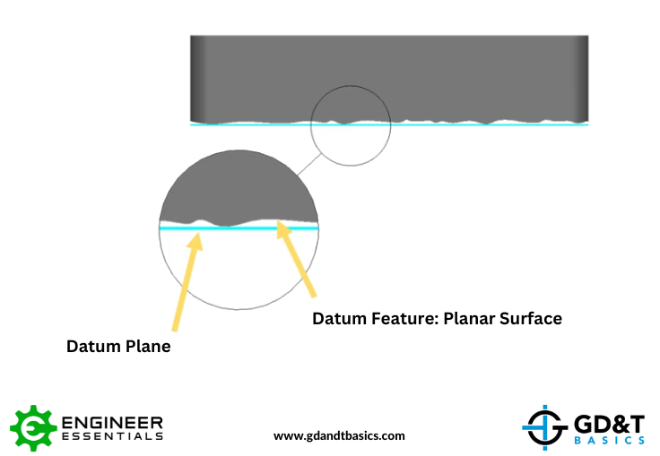
Figure 1: Datum Plane from a Planar Surface Datum Feature
A Cylinder as a Datum Feature
When a cylinder is a datum feature, the highpoints on the surface of the cylinder will be used to create a perfect envelope. The axis of this perfect envelope will be the resulting datum.
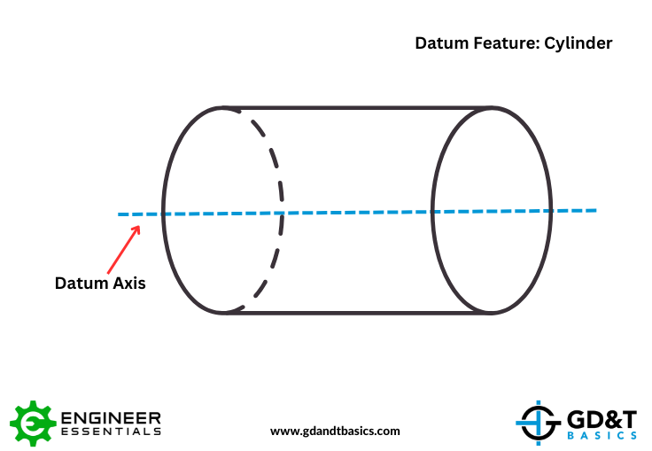
Figure 2: Datum Axis from a Cylindrical Datum Feature
A Sphere as a Datum Feature
When a sphere is used as a datum feature, the center point of the sphere is the resulting datum point.
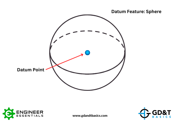
Figure 3: Datum Point from a Spherical Datum Feature
A Cone as a Datum Feature
A cone as a datum feature is a little bit different. The resulting datum will consist of the center axis and a point. (The datum point being the converging point of the cone.) This point is used in tandem with the axis.
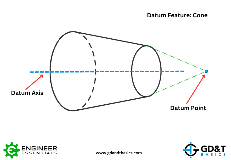
Figure 4: Datum Axis and Datum Point from a Conical Datum Feature
As you can see, some datum features utilize points, lines, and axes differently. To answer our students’ question above, we need to understand how this “single point” is created – what datum feature is being represented by this single point datum?
Let’s walk through an example to see if there is a case for using a datum point as a secondary datum in a feature control frame.
Example: Rotating Cylindrical Shaft with Conical End
In this example, we are looking at a rotating shaft with two bearing surfaces and one end of the shaft having a conical taper. From the drawing shown in Figure 5, you can see that the two bearing surfaces are indicated as Datum Features A and B, and the cone is indicated as Datum Feature C.
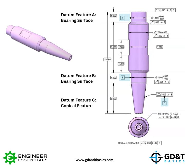
Figure 5: Drawing of Rotating Shaft with Conical Tapered End
In our feature control frames, notice that the primary datum is listed as A-B. Because both bearing surfaces (datum features A and B) work together, they will be equally as powerful in the assembly in setting the axis of rotation. So in this case, we would create one datum axis from both datum features, and indicate this as Datum A-B.
In Figure 6 below, we show how the assembly condition could be simulated for inspecting the shaft. The two bearing surfaces would be set on V-blocks and rotated, creating one axis from the two features, just as it would be when assembled.
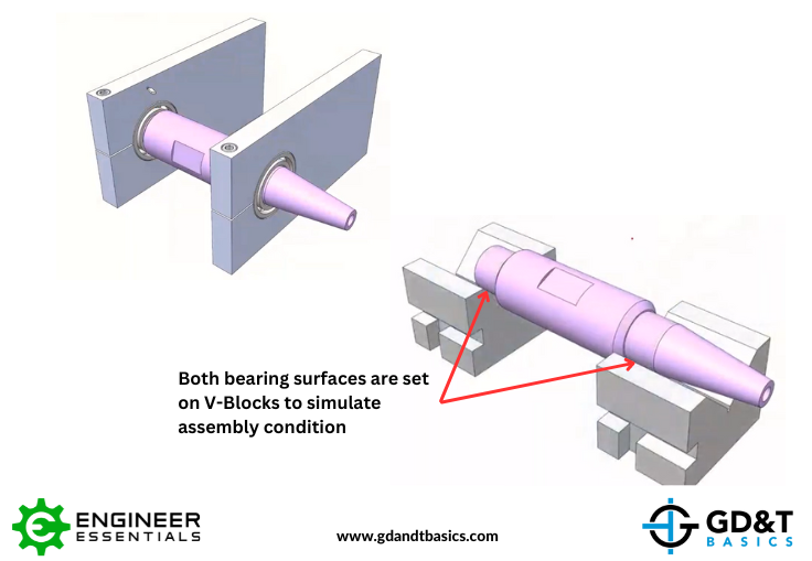
Figure 6: Assembly Condition and Inspection Set-Up
In creating this datum axis, we are locking down four degrees of freedom: two rotations (v and w) and two translations (Y and Z). Rotation “u” and translation “X” are not locked down using our primary datum A-B. This is illustrated in Figure 7.
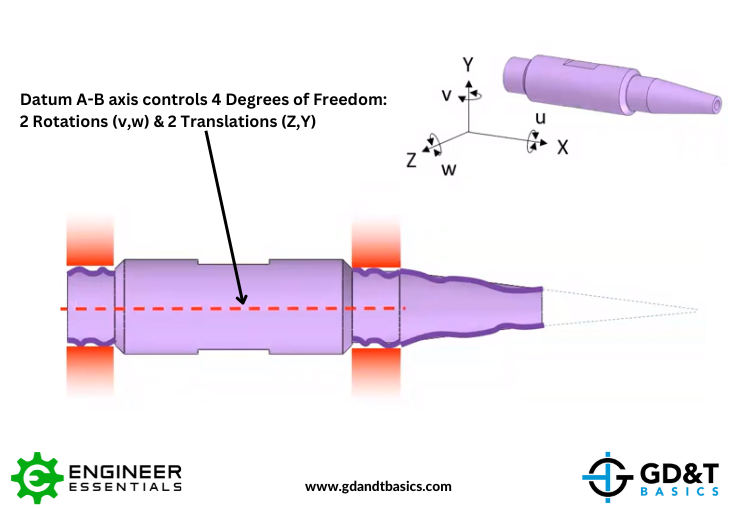
Figure 7: Datum A-B Axis Degrees of Freedom Controls
Next, we will look at our secondary datum feature, Datum Feature C, to add more control. We know that as a cone, Datum Feature C will create a datum axis and point. The axis of the cone controls the same degrees of freedom as axis A-B, but because of datum order precedence, Datum A-B will override any control that Datum axis C has. Therefore, we don’t get any additional control from the axis of the cone. However, we still need to look at the datum point.
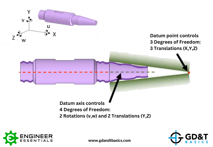
Figure 8: Datum C Axis and Point Degrees of Freedom Controls
A datum point controls three degrees of freedom – the three translations X,Y, and Z. Because Datum axis A-B is already controlling translations Y and Z, Datum point C can only control the X translation. As a datum point has no control over rotation, the rotational degree of freedom, u, is still open. This is acceptable because there is no feature on this part that requires clocking – the flat on the shaft doesn’t need to be located to anything else. Adding a rotational clocking feature to lock down that last degree of rotation would be unnecessary.
Conclusion
The answer to the question, “Can a single point (without clocking) be used as a secondary datum in a feature control frame?,” depends on the setup and function of the part. As we have shown in our example above, a datum point can be used as a secondary datum feature when additional rotational control is not required.
For a more detailed explanation in answer to this question, watch the webinar recording linked below:
The one-page GD&T reference that you will use every day
A visual breakdown of every core GD&T symbol and what it controls, all on one page. Bookmark it. Print it. Actually use it.
Download the Chart