

There are many great reasons why engineers & designers benefit from knowledge of Geometric Dimensioning & Tolerancing (GD&T). But today, we want to share with you just one reason that is particularly interesting.
Even though GD&T is simply a method of communicating inspection criteria & dimensional specifications on 2D drawings, learning to use it can be helpful outside the context of drafting. It can also improve your repertoire of design strategies and avoid common design errors. Understanding the ideas behind GD&T can literally help you design functionally better parts!
But how so, specifically?
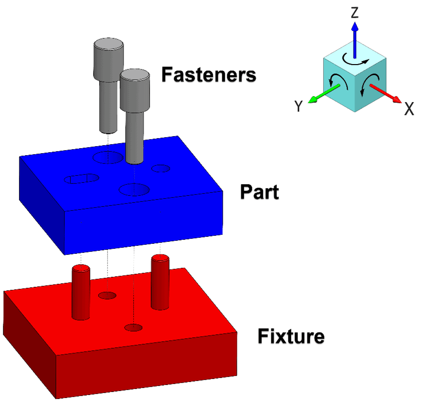
On model 1 above, the blue piece represents a simple mechanical part that you, as an engineer, might want to create. It has two counterbored holes designed with clearance for fasteners. It also uses the common hole & slot combo strategy for locating it within an assembly, which is great for being super simple to design & manufacture.
The red block with two pins could be referred to by many names in this context: A datum feature simulator, a mating part, or an inspection fixture. The two gray shouldered pins represent a socket head cap screw. An inspection specification for the blue part might look something like this:
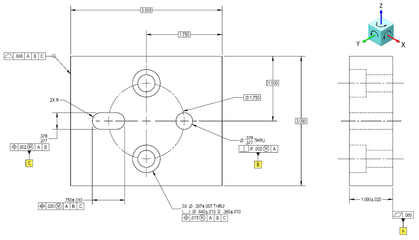
This drawing clip shows the design intent for this part. Datum feature A, which is a plane, constrains the part’s Z-translation and its ability to rotate around the X or Y-axis. Datum feature B, which is an axis, constrains translation about the X & Y axes, and finally, Datum feature C, which is a midplane, constrains rotation around the Z-axis. That totals 6 DOF (degrees of freedom) and fully constrains the part.
Take note that if the slot (datum feature C) was instead designed to be a circle, then it too would be attempting to constrain the part along its already fully located Y-axis. There would be no margin for error on the distance between the pins, and the result would likely be difficult to press into place.
Example 1:
A common mistake made by new designers is expecting precision when using fasteners as the primary means of locating parts within assemblies. If function requires the use of the fasteners as a datum feature, then we should consider it. The problem with doing this is that the mating parts are imperfectly constrained relative to one another.
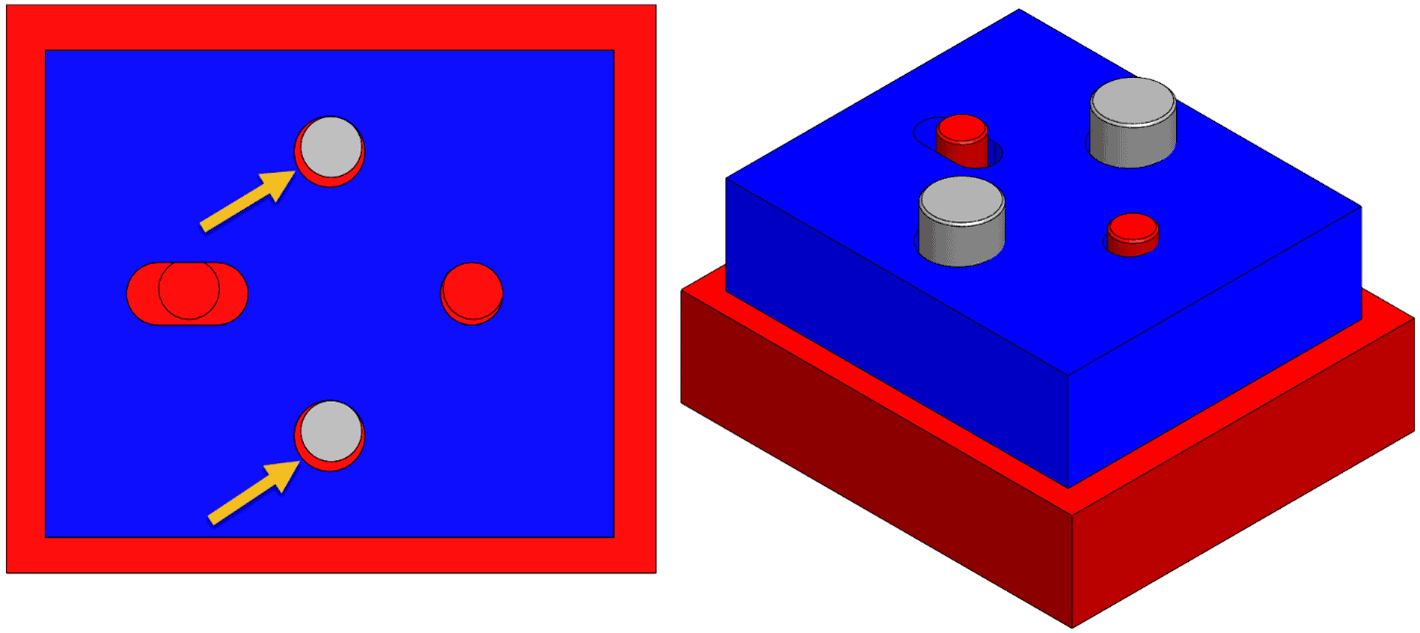
This is because fasteners need some amount of clearance to ensure that they will fit through holes – you don’t want them to get jammed in when being assembled on the line! This means if fasteners do the locating, then there is some uncertainty in the final resting position of the part. This is easily illustrated using our model. If we fasten the blue part to the gray block without constraining to the two pin locators, the block can still wiggle in place! (See section view 1 of the model below, with the arrows indicating the source of the wiggle room).
OK, how about trying to solve the wiggle problem by simply adding more fasteners? Well, we kept our model simple so it doesn’t look like swiss cheese covered in holes, but we can still illustrate what would happen if we twist the blue part in place as much as the screws will allow, then try to install the tight tolerance locating pins. (See section view 2 of the model below).
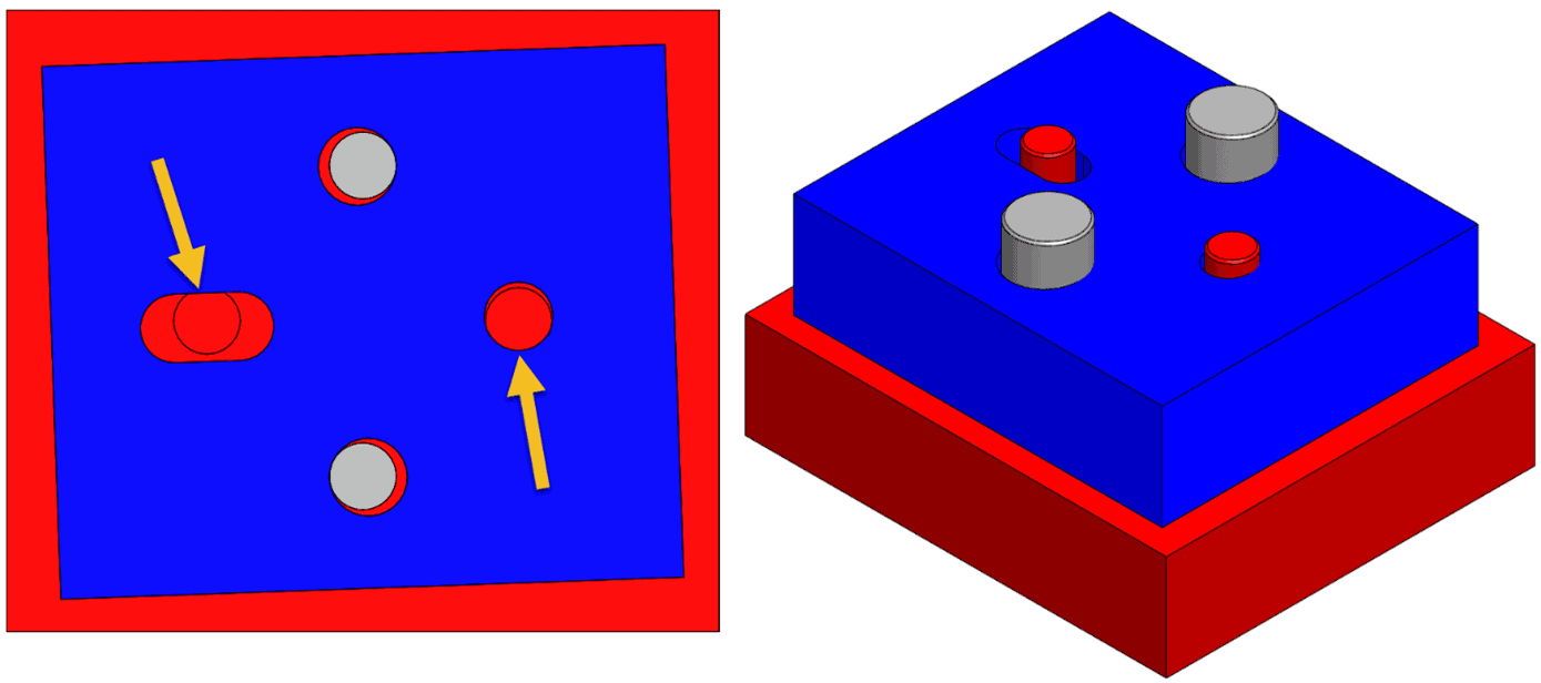
Notice how their holes don’t line up enough to install them because the pins now interfere too much with the part? The assembly order of operations resulted in an over-constraint because different screws attempted to constrain the already fully constrained X or Y-axis. The part no longer wiggles, but the resulting resting position is indeterminate, which is not conducive to precision control.
The idea of designing robust datum features that provide adequate constraint of all six degrees of freedom of a part is something that students of GD&T internalize and keep in mind during the design phase. This lesson is of critical importance when designing high precision assemblies that contain many mating parts because tolerances stack up. The more links you have in a chain, the less control you have in the position of those links. For best results, fasteners should be retaining elements only, so they don’t affect the position of the part!
Example 2:
Referring again to our same example assembly, what do you think the effect would be if the part & fixture were redesigned with the two pin locators farther apart? Or if the pair of pins were shifted from the center toward the side of the part?
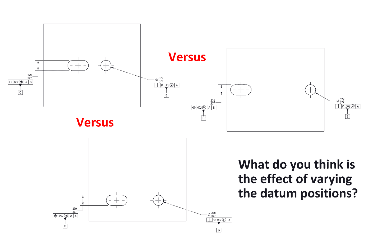
Folks who understand GD&T know what constitutes a stable set of datum features. Keeping the locating pins positioned farther apart from others gives them a wider stance and allows them to more effectively constrain the part.
Similarly, keeping the locating pin pair close to other features of importance is a smart design choice because positional accuracy decreases with distance from the assembly locators. (The degree of accuracy varies on many things including scale, the number of parts in the assembly, and manufacturing method. This is a key concept for the practice of Design for Manufacturability.
It should be clear at this point that where precision mechanical design strategy is concerned, knowledge of GD&T is a useful trick to have up your sleeve!
Do you have any other good engineering tricks up your sleeve? If so, we’d love to hear them, so let us know in the comments below and be sure to share these tips with your friends!
Interested in Learning More About How GD&T Can Help?
Check out our various training options.
Click here for information about our GD&T Courses