
What is “Design for Manufacturability?”
Who should be involved in designing for manufacturability?
When designing a part for manufacturability, everyone who has a stake in the product should be involved. This includes more than the design and manufacturing engineers. Some other departments involved with the product include Quality (inspection), Purchasing (material procurement), and even Marketing. The vendors from which you would be buying materials and components should also be consulted. Having all stake-holders involved during the design process will help potential problem areas come to light earlier in the process. This allows those issues to be resolved during the design phase.

In addition to having all stakeholders represented in the design phase, there needs to be effective communication. All parties need to understand what is being communicated through the engineering drawings. If any parties do not understand how to read the engineering drawings, problems with the design may be overlooked.
What influences manufacturability and cost for a part?
There are many things to take into consideration when creating a new design. As was mentioned above, the more stake-holders involved during the design phase, the more potential issues will come to light and be resolved early on. This in itself is a huge cost savings when considering the “Rule of 10.”
The Rule of 10 is the idea that at each new phase of product development, the cost to make a change is 10 times what the cost would have been to change the product in the prior phase. Say that the product development timeline consists of design, testing, then production. By the Rule of 10, making a change during the testing phase would cost 10 times the amount of making that change in the design phase. And if that change wasn’t made until production, it could cost 100 times the amount of making the change during the design phase. This clearly shows the importance of having a team that is knowledgeable in all aspects of the design.
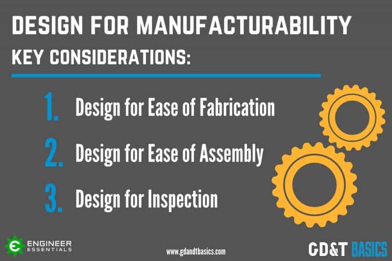
So, what are the key considerations when designing for manufacturability?
- Design component parts for ease of fabrication.
- Design for ease of assembly.
- Design for inspection.
Key Considerations in Design for Manufacturability
1. Design Component Parts for Ease of Fabrication.
When designing a part to be easily manufactured, optimal materials, part tolerances, and manufacturing processes must be determined.
Items to consider:
Use off-the-shelf parts: One of the first things to consider is whether a new part must be created, at all. Is there an off-the shelf part that would work? Using an off-the shelf part, rather than designing a new one, would result in lower cost.
Use common parts: If you can’t use an off-the-shelf part, is there a part currently being used on other assemblies that will fit your function? Using common parts not only prevents you from having to create a new design, but it also reduces the number of parts that must be kept in inventory.
Material considerations: Another consideration is the material that the part is to be created from. Try to use common materials, which are easier to procure. Also, select materials that your existing manufacturing equipment can handle.
Concurrently design the part and its required tooling: Design the tooling required to produce your part as you are creating your part design. To do this, you must understand the manufacturing process and the capabilities of the manufacturing equipment that will be used in producing your part.
Optimal part tolerances: Focus on the function of the part to determine optimal part tolerances. Using tolerances that are too tight will increase the cost of producing the part, as well as result in more part rejects. Part tolerancing also affects the assembly of the part into a product. Tolerancing for assembly is discussed in the next section.
2. Design for Ease of Assembly
When designing for manufacturability, not only do you need to think about how the individual part will be produced, but also how it will be assembled into the top-level product. You need to think about the fit of the part, and how to make the assembly as simple as possible.
Optimal tolerances: To ensure the proper fit of a part within the assembly, the part needs to have optimal tolerances specified on the drawing. Drawings incorporating Geometric Dimensioning and Tolerancing (GD&T) do just that. When GD&T is used in a design, the focus is on the function of the part, and tolerances are determined based off of the functional requirements.
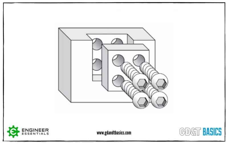
Take the assembly shown in Figure 1 as an example. In this assembly, a part is designed with four holes. The purpose of the four holes is to attach the part to an assembly using bolts. The goal when dimensioning the position of the holes would be to make sure the centers of the holes are not too far away from their targets.
If we were to use coordinate dimensions, the position tolerance zone of the hole would be a square, as shown in Figure 2. The corner of the square would be the largest distance away from the targeted center of the hole. This distance is not the same from the center all around, because it is a square tolerance zone. The holes and the bolts are both round, so functionally, there is no reason that the tolerance zone could not extend the max distance (target center of the hole to the corner of the square) all around. However, this can be done by using GD&T.
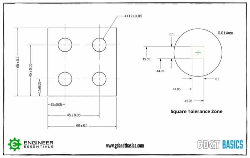
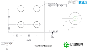
With GD&T, a round tolerance zone for the position of the hole would be shown by using the position symbol and diameter symbol in the feature control frame. Figure 3 shows this same part dimensioned using GD&T. Having a round positional tolerance zone, rather than a square one, results in a tolerance zone that is 56% larger, yet still meets the functional requirements. Having a larger tolerance results in a part that is easier and cheaper to produce. This concept is explained more in-depth in this article: Advantages of GD&T vs. Coordinate Tolerancing.
In addition to tolerances, when designing a part that will be assembled into another product, consider ways to make the assembly as straightforward and uncomplicated as possible.
Tips for individual parts:
- Make part differences obvious: If you have multiple parts that are similar, design the parts so that the difference between parts is obvious. For example, this could be done using markings, or even different colors. This can help prevent the wrong part from being placed into an assembly.
- Part Symmetry: If it is possible, design the part with symmetry so that it does not need to be oriented in a certain way. This prevents a part from being put on backward, because there is no “back side.”
Tips for the assembly design:
- Reduce the total number of parts in the assembly: Having fewer parts to assemble can reduce the assembly time, and reduce the potential for errors.
- Create the top-level design using subassemblies: Using subassemblies simplifies the top-level design. It reduces the number of parts to be assembled onto the top-level design. An additional benefit is that updates can be made to the subassembly design without affecting the top-level design.
- Include easy and quick fastening methods.
3. Design for Inspection
The third consideration when designing for manufacturability is to design for inspection.
Designing using GD&T allows us to indicate what is functionally important, how to establish the inspection set-up, and gives the ability to use functional gauges in the inspection of the part.
Clearly indicate functional requirements:
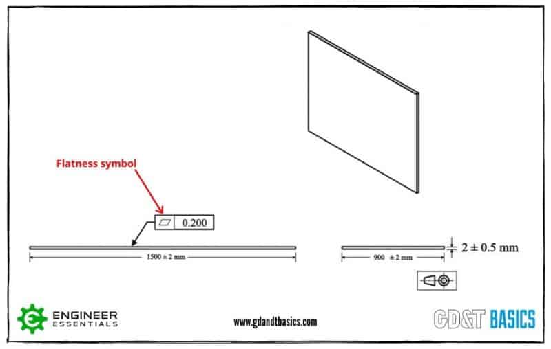
When a design is created using GD&T, the drawings clearly show what is functionally important. This drawing of a mirror is a great example of this. Let’s say that the entire surface of a mirror must be flat within 0.2mm to avoid a wavy surface. Using coordinate dimensions, you could try to achieve a flat surface by adding a tight thickness tolerance. However, the thickness could be uniform and the mirror be shaped like a potato chip! With GD&T, you can show the intent of the design, which is a flat surface, by using the flatness symbol. This is shown in Figure 4.
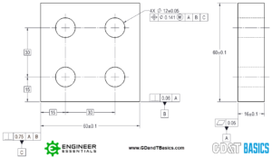
Indicate inspection setup on drawing: When using GD&T in your design, not only are the part dimensions shown, but the drawing also indicates how the part is to be set up for measurement. This is done by including datums on the drawing. A datum is a theoretical plane, axis or point location that dimensional tolerances are referenced to. It is called out on a drawing as a capital letter with a box around it. An example of a drawing using datums is shown in Figure 5.
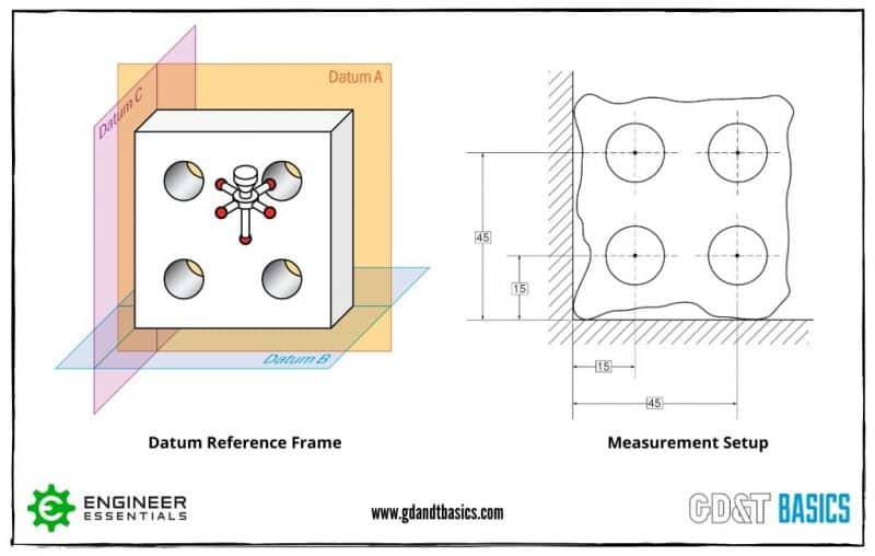
To inspect this part, you would use a datum feature simulator. A datum feature simulator is a piece of inspection equipment with a surface that contacts the datum feature (part surface) to simulate a perfect surface/datum. Figure 6 shows the datum reference frame and measurement set-up for the part shown in Figure 5. By securing your part to the datums using a datum feature simulator, you are specifying how you want the part to be measured to mimic the actual function of the part. This results in repeatable measurements. In addition to this, if the drawing is set up where multiple features are related to the same datums, the inspector does not have to repeatedly change the measurement set-up.
Design for use of functional gauges:
The third consideration when designing for inspection is to design for ease and quickness of inspection. This can be accomplished using functional gauges. Functional gauges allow the part to be inspected right on the line, decreasing the inspection time.
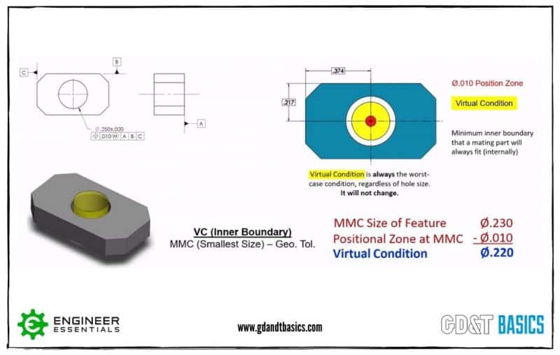
To create a design that can be inspected using a functional gauge, you must design for Maximum Material Condition (MMC). A feature is at maximum material condition when it contains the largest amount of material allowed by its size tolerance. So, a hole would be at MMC when it is at its smallest allowable size, and a pin would be at MMC when it is at its largest allowable size.
To create a functional gauge, you would use the MMC and the position tolerance of the feature to calculate the worst-case condition that would still allow the mating part to fit. This worst-case condition is called the Virtual Condition (VC). The functional gauge can then be created based off of the Virtual Condition of the feature. Figure 7 shows an example of calculating the Virtual Condition of an internal feature (hole).
Summary
Three areas must be considered when creating a design:
- Ease of fabrication of the component part
- Ease of assembly
- Ease of inspection
Overwhelmed by the Complexity of Engineering Drawings?
Learn at your own pace and apply it with confidence in the real world.
Start Learning Today
THIS INFORMATION IS EXTREMELY USEFUL.
THE TECHNIQUE TO EXPALIN TEXTUALLY AND GRAPHICALLY IS EXCELLENT.
I HAVE BEEN APPLAYING GDT FOR MORE THAN 25 YEARS AND I CONTINUE TO LEARN EVEN MORE..
Esta información es de enorme utilidad práctica. La técnica para explicar textual y gráficamente es excelente. Yo llevo más de 25 años aplicando las GD and T y sigo aprendiendo aún más.
THIS INFORMATION IS EXTREMELY USEFUL.
THE TECHNIQUE TO EXPALIN TEXTUALLY AND GRAPHICALLY IS EXCELLENT.
I HAVE BEEN APPLAYING GDT FOR MORE THAN 25 YEARS AND I CONTINUE TO LEARN EVEN MORE..