

When applying position tolerances to countersunk fixed fastener assembly conditions, the position of the through hole for the fastener and the countersink feature for the fastener head must both be taken into consideration for proper assembly. Our design must not only ensure assembly, but also that the fastener head sits flush or below the surface of the part.
Let’s look at an example to illustrate how to apply position tolerances to an assembly such as this. We will be looking at the fastener assembly for the door shown below in Figure 1, which includes a sight glass, a collar that holds the sight glass against the door, and fasteners that attach the collar to the door. The collar has countersunk through holes and the door has threaded holes to receive the fasteners.
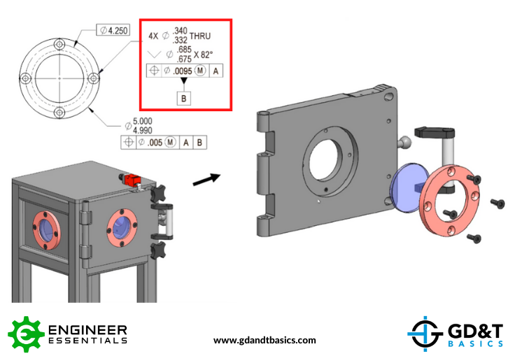
Figure 1: Door Assembly
Notice in Figure 1 that the feature control frame controls the position of both the conical countersink as well as the through hole with a positional tolerance of .0095. We are going to explain below how we determined these values to ensure proper assembly of the countersunk fastener.
Determining Position Tolerance
Let’s look at the cross-section view of the fastener assembly, shown in Figure 2. You can see that with no positional error, the screw passes through the through hole of the red collar and threads into the threaded hole in the gray door, and the head of the fastener is flush with the surface of the collar.

Figure 2: Cross-section of Fastener Assembly with No Position Error
However, in a real-world scenario, we will have positional error. To ensure that the threaded fastener assembles correctly, we must determine the allowable position tolerances of the holes.
To do this, we use the fixed fastener formula, T1 + T2 = H – F, where:
- T1 = the position of the through hole
- T2 = the position of the threaded hole
- H = the MMC size of the through hole
- F = the MMC size of the fastener thread
The values for the fastener itself (the MMC of the fastener thread and the MMC of the fastener head) can be found in the Machinery’s Handbook or the fastener specification. However, the designer has control over the MMC of the through hole. The designer will choose whether a standard fit, loose fit, or tight fit is desired the and select the MMC of the through hole accordingly. The values for the fastener and the holes for our assembly are shown in Figure 2.
By plugging in the MMC of the through hole and fastener thread, our equation would be:
T1 + T2 = .3320 – .3125 = .0195
This means that .0195 is the amount of tolerance that we can assign to BOTH the position of the through hole (T1) and the position of the threaded hole (T2). The division of the total position tolerance between T1 and T2 is determined by the manufacturing capabilities, the designer’s preference, etc. For our example, we will apply the tolerance near evenly, so that:
- T1 (Through hole position tolerance) = .0095
- T2 (Threaded hole position tolerance) = .010
Radially, this gives us a through hole position tolerance of .00475 and threaded hole position tolerance of .0050, as indicated in Figure 3. However, we can also see in Figure 3 that though the fastener assembles, the fastener head now does not sit flush with the surface of the part – this is due to a shift in alignment.
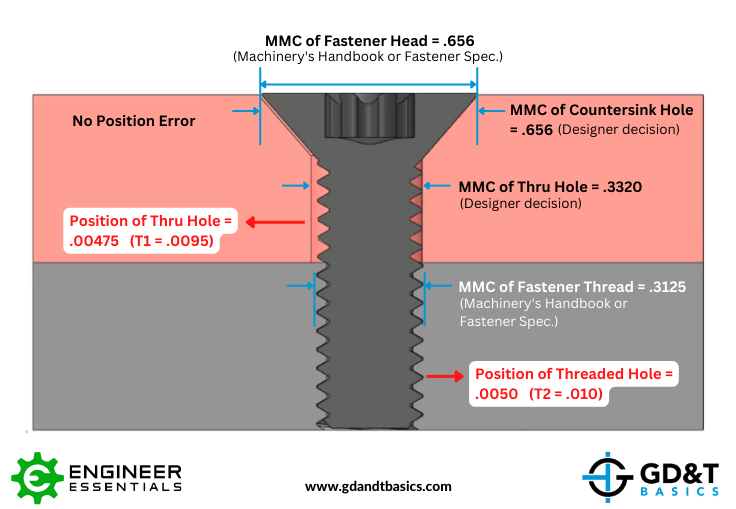
Figure 3: Fastener Assembly – Fastener Head not Flush
Ensuring that the Fastener Head Sits Flush
What can we change to ensure that the fastener head will sit flush or below the surface of the part? We can increase the diameter of the countersink hole, allowing for more room for the fastener to sink below the surface. However, if the countersink hole has any positional or size error, the fastener still may not sit flush. Therefore, to ensure we have a flush fastener, we must determine the positional and size tolerance for the countersink diameter.
To do this, we will once again use the fixed fastener formula, T1 + T2 = H – F, but in this case:
- T1 = the positional tolerance of the countersink diameter
- T2 = the positional tolerance of the threaded hole
- H = the MMC of the countersink diameter
- F = the MMC size of the fastener head
If we want to control both the through hole and the countersink hole with the same feature control frame and the same positional tolerance, the allowable position error for our countersink hole has to match that of the through hole. In our previous calculations, we determined this number (T1) to be .0095.
With our F value known (the MMC of the fastener head is determined from the Machinery’s Handbook or fastener specification), and our T2 positional tolerance of the threaded hole having been determined from our previous calculations, we only have “H,” the MMC of the countersink hole, left to calculate.
Therefore, our fixed fastener equation is:
T1 + T2 = H – F => .0095 + .010 = H – .656
Solving for H, we find the MMC of the countersink hole to be .6755. So as long as our countersink diameter is larger than .6755, our fastener will sit flush with the surface as shown in Figure 4.
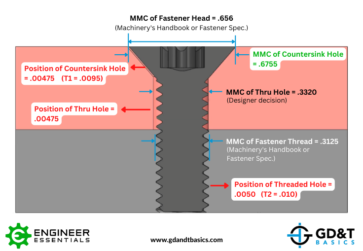
Figure 4: Fastener Assembled and Flush with Surface
Conclusion
The amount of position tolerance that we have available to ensure assembly is determined by the values we choose for the MMC of the hole and countersink, in comparison to the MMC of the fastener. When we are able to increase the allowable amount of clearance between the fastener and the through hole, we are able to increase the positional tolerance. In the same way, increasing the diameter of the countersink hole increases the opportunity for the fastener head to sit flush with the surface.
By using the fixed fastener formula, we are able to determine the position tolerance needed to ensure assembly of the fastener though the holes. By next applying the fixed fastener formula to the countersink hole, we are able to ensure that the fastener head will sit flush with the surface of the part.
Check out Jason’s video for an in-depth explanation of applying Position tolerances to countersunk fixed fastener assembly conditions:
The one-page GD&T reference that you will use every day
A visual breakdown of every core GD&T symbol and what it controls, all on one page. Bookmark it. Print it. Actually use it.
Download the Chart