

In this question line video, Jason explains how to control radial position with a composite tolerance by walking through an example of a pattern of holes on a cylinder.
Frequently, when composite position is called out on a pattern of holes, the holes are on a flat surface and the axes of the holes are parallel to each other. But what if the axes of the holes are not parallel, as in the case of a pattern of holes on a cylinder? In this video, Jason answers the following question submitted through our instructor question line:
“Can I control the pattern of holes on the side of a cylinder with composite position even though the axes of the holes aren’t parallel to each other?”
Radial True Position with Composite Tolerance
In Figure 1, we see a pattern of four holes on the outside of a cylinder that is being controlled with composite position. In the upper feature control frame, the holes are being controlled with position with respect to Datums A and B. The lower frame then refines the position with respect to Datum A. On the drawing, Datum Feature A is indicated as the OD of the cylinder, resulting in Datum Axis A. Datum Feature B is indicated as the bottom surface of the cylinder, resulting in Datum Plane B.

Figure 1: Hole Pattern Controlled by Composite Position Tolerance
Upper Frame
We first look at the upper frame of the composite feature control frame. This upper frame utilizes the datum reference frame AB to fully constrain the holes. Through the upper frame, we are controlling the holes’ perpendicularity to Datum Axis A, their convergence with Datum Axis A, their rotation about that axis, as well their location with respect to each other. With Datum B listed as a secondary reference, we are also controlling location back to Datum B. Figure 2 shows the tolerance zones for the holes based on the upper frame. These tolerance zones are locked in and centered at true position.
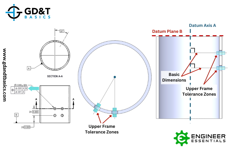
Figure 2: Tolerance Zones for Holes Based on Upper Frame Only
Lower Frame
In a composite feature control frame, the lower frame only controls orientation. In our drawing, we see that the lower frame gives us a .001 diametric tolerance with respect to Datum Axis A. The orientation we are controlling with the lower frame is the perpendicularity of the axes of the holes to Datum Axis A. Because the holes are no longer located to Datum B, they are allowed to move up and down, as shown in Figure 3.
Figure 3: Lower Frame Tolerance Zones are Only Perpendicular to Datum A
Because the lower frame only controls orientation, the holes are also no longer being controlled in location to Datum A. This means that the axes of the holes no longer have to converge, or be radially located, with Datum Axis A. Since the holes are a pattern, the only requirement is that they stay 30 degrees from each other, as indicated in the basic dimension. This allows the holes to move as shown in Figure 4.
Figure 4: Allowable Movement of Hole Pattern
As long as the axes of these holes land within the upper frame tolerance zone (shown in blue) and lower frame tolerance zone (shown in purple), they will pass inspection. In summary, this composite feature control frame is requiring that the pattern, the hole-to-hole location, be held tighter than the location of the holes on the part itself.
The one-page GD&T reference that you will use every day
A visual breakdown of every core GD&T symbol and what it controls, all on one page. Bookmark it. Print it. Actually use it.
Download the Chart