

Geometric Dimensioning and Tolerancing, and the concept of “True Position,” originated due to a rejection of functional parts as a result of coordinate dimensioning. Let’s look at a simple assembly to illustrate why this is true, and how GD&T Position takes care of this problem.
The Problem with Coordinate Dimensions
In the below assembly, we have fasteners that pass through an aluminum channel and thread into the red block. The drawing for the aluminum channel uses coordinate dimensions, and the thru holes have enough clearance to allow for some deviation of the holes with respect to the threaded holes in the red block.

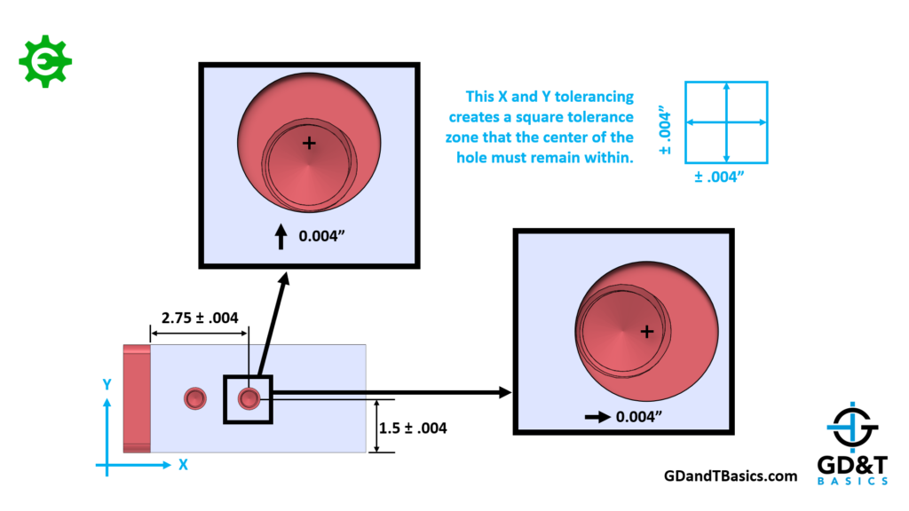
Let’s determine the tolerance values that must be applied to the dimensions to ensure that there will be no interference with the fastener during assembly. For this example we are assuming no error in position of the red threads for the sake of simplicity. However this deviation can be taken into account with additional analysis. If we allow the hole to drift in the X direction of the aluminum channel until all of the clearance is utilized, we see that the maximum deviation we can have is .004”. This same maximum deviation is also found in the Y direction. This creates a square tolerance zone that the hole must stay within.
But what if the hole drifts simultaneously in the maximum amount for both the X and Y directions? You can see that though it would pass inspection, there would be interference with the fastener during assembly. Therefore, you would need to determine the tolerances required to prevent this worst-case scenario.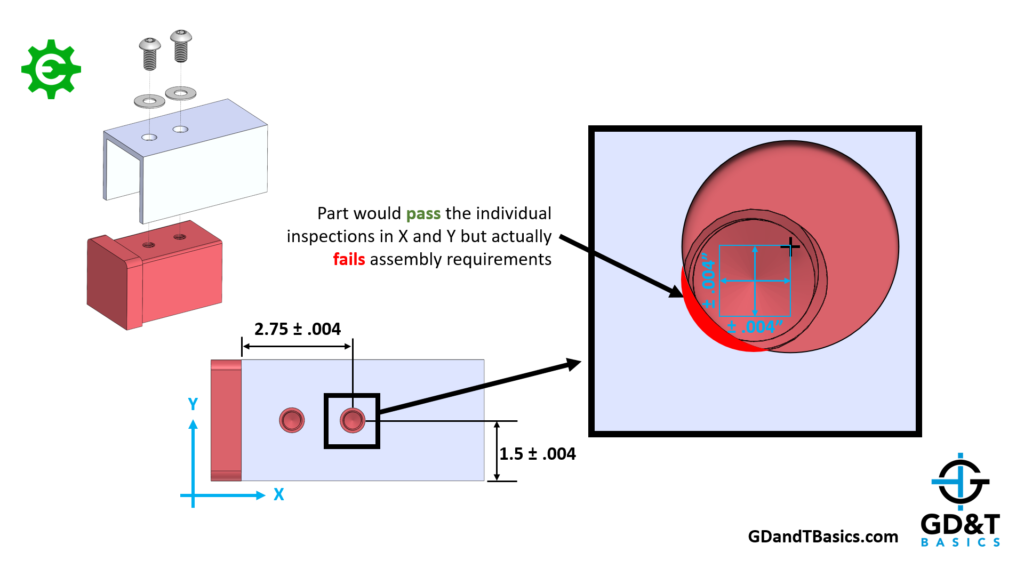
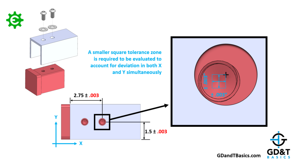
Through some simple trigonometry we find the required tolerances to ensure assembly in the worst-case scenario to be +/-.003 in the both the X and Y directions.
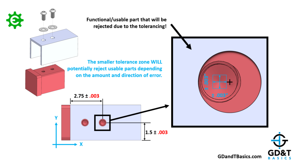
Though this has ensured assembly, we are now requiring the rejection of functional parts! We saw earlier that that if the hole deviated .004 in one direction only that there would be no interference during assembly.
GD&T Position Control Solves this Problem!
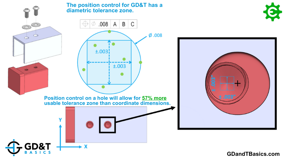
Let’s convert this to a GD&T drawing to show how the GD&T Position control solves this problem. GD&T Position tolerance is diametric, so using the Pythagorean Theorem, we can convert the +/- .003 rectangular tolerances from the previous example to a total diametric tolerance of .008. This is the Position tolerance value found in the feature control frame. We would then change the toleranced dimensions locating the holes in the previous example to basic dimensions (indicated as boxed dimensions), establishing the True Position of the holes.
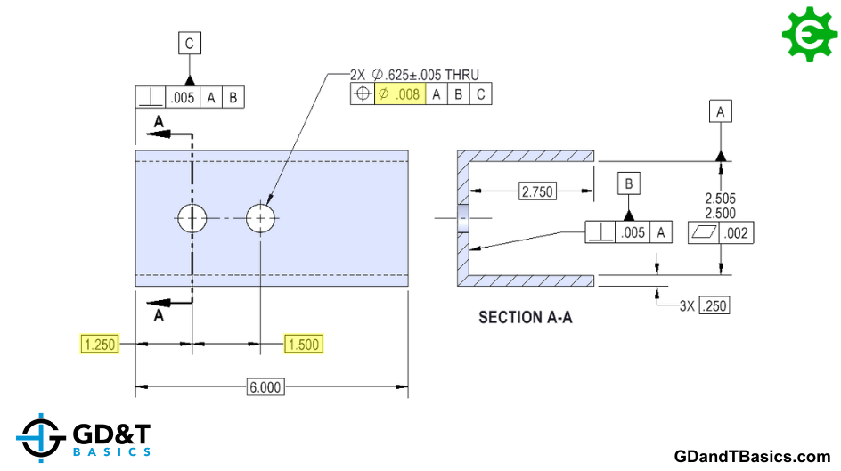
By switching to a diametric tolerance, we are allowing all of the functional locations to fall within our tolerance zone, and allowing 57% more tolerance for the location of the hole!
Note: The GD&T terms “True Position” and “Position” are widely used interchangeably. However, the ASME Y14.5 standard defines “Position” as the total permissible variation that a feature can have from its “true” position, where the true position is the nominal value defined by basic dimensions. In other words, the GD&T Position tolerance is how far a feature’s location can vary from its “True Position.”
Inspecting Position
The method of inspection when using GD&T Position is the same as when inspecting coordinate dimensions. We will still measure the deviation of the feature in the X and Y directions. However, these deviation measurements must be converted into a single diametric value to determine whether the feature passes inspection. You could do the math yourself… or you could use our convenient True Position Calculator!
The one-page GD&T reference that you will use every day
A visual breakdown of every core GD&T symbol and what it controls, all on one page. Bookmark it. Print it. Actually use it.
Download the Chart